This design is a solid-state replacement for thermal relay K-1 in the AM-65/GRC audio amplifier. When the AM-65 is used as a power supply for the RT-70 transceiver, K-1 protects the filament chain by reducing the filament current if the filament voltage rises too high. This can happen when certain tube filaments burn out, and can cause a chain reaction that burns out many other tube filaments. The original part is described as follows in the service manual for the AM-65/GRC (TM 11-5039):
K-1 RELAY, thermal: SPST normally closed; cont rating 2 amp max; silver cont; single wnd heat coil, operates at 6.9 v DC w/ 1 amp cont load, release at 2 to 3.5 v, heater current 250 ma w/6.9v applied, ins; coil and cont leads terminate in octal base; 1.275″ diam x 2 7/8″ lg excluding base cont and locating pin; mts by means of octal base; operates within 10 sec; incl in type T-9 bulb w/std octal base; Raytheon #CK-118; Fed Tele & Rad part /dwg #GH-2392-12.
The original Signal Corps part number is 2Z7598-129.
The original relay contains a wire whose tension keeps the relay contacts open. This wire is placed in parallel with the tube filaments. If the applied voltage (which is determined by the regulated current passing through the filaments and thermal relay) rises above the trip threshold, the wire expands enough to let the contacts open. The contacts short out a resistor in the AM-65 when they are closed. Once they open, this resistor is placed in series with the tube filaments, thus droppng the voltage applied to them (though generally not enough to allow the relay to close again).
This solid state replacement uses a 5VDC relay from Radio Shack, driven by an SCR. The Zener diodes set the trip threshold. When the applied voltage rises enough to forward-bias the regular diodes and break down the Zener diode, the SCR will trigger and turn on the relay. The resistors simulate the resistance of the heating wire in the original relay. The relay will drop out when the applied voltage drops too low, but the SCR will remain on (and re-energize the relay if the voltage rises again) until the power is removed.
I normally avoid modifying vintage radio gear, and I do not like to use non-original replacement components. However, my first priority is usually to get a radio back on the air. I designed this unit to replace the hard-to-find thermal relay in my AM-65 audio amplifier without damaging or irreversably modifying the amplifier. Because this is a plug-in unit and does not require any other circuit modifications in the AM-65, I can easily replace it with the correct relay at any time.
CONSTRUCTION DETAILS:
Here is the schematic diagram, in both Adobe PDF and Postscript formats:
 |
ck118.pdf | (35k) |
 |
ck118.ps | (36k) |
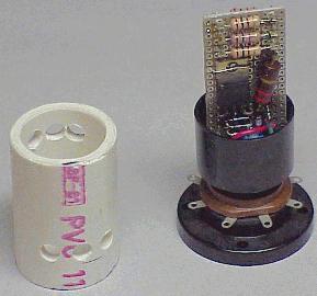
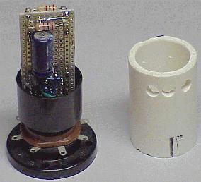
I built my prototype on a small piece of perforated circuit board, which I trimmed to snugly fit inside a short piece of 1″ PVC pipe. I mounted the board inside an octal tube base, and cut a piece of pipe such that when slipped over the end of the board, the entire assembly would have the same dimensions as the original relay. I drilled holes in the pipe to allow air to flow through the assembly. I attached the pipe to the tube base with electrical tape. In operation, the unit gets very warm and the tape softens, so I plan to replace the tape with glue or epoxy. The design was based on parts in my junk box, so you may wish to modify it accordingly.
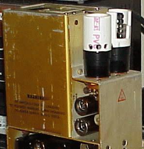
The pictures below show front and rear views of the relay with the PVC pipe removed, and both the thermal relay and a solid-state ballast tube replacement installed in an AM-65 (the relay itself is buried down inside the octal tube base):
ADJUSTMENT:
This design does not have any adjustable components. You should prototype the circuit before building it, verify that it trips at an acceptable voltage, and remains tripped until the voltage drops below an acceptable threshold. You may need to modify the diode chain in order to change the trip threshold.
OTHER USES:
You should be able to adapt this design for use in other equipment which uses similar thermal relays. You may need to change the tube base pin connections to match the pinout and polarity of a given piece of equipment.