Please note that I do not have any original manuals for this set, and I do not even have a complete set of copied manuals (for example, I do not have any aligment procedures, and I would have great difficulty understanding them even if I had them due to my very poor command of the German language). I cannot provide any further information beyond what is described here at this time, and I cannot provide manual photocopies or other printed information at this time. This page truly contains everything I know about the SEM-25!
Please comment me if you discover any errors in this paper.
I hope you find this information useful!
Description
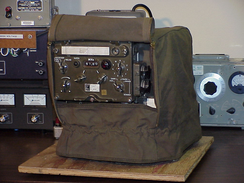
The SEM-25 is a West German short-range tactical vehicular VHF FM transceiver which was introduced in the 1960’s, and was apparently used until at least the 1980’s. Although surplus SEM-25 radios are not yet very common in the U.S., some have recently appeared on the U.S. surplus market from vendors such as Murphy’s Surplus Warehouse.
The SEM-25 covers 26.00 to 69.95 MHz, in 50 kHz steps. It is all solid-state, except for three tubes in the transmitter power amplifier. A SEM-25 system will typically consist of at least the following items:
- Transceiver chassis
- Control box (may be mounted on front of transceiver, or remotely)
- Mounting/power supply
- Power transient suppressor
- Antenna tuning unit
- Antenna
- Audio accessories ranging from a simple handset to several junction boxes and headsets
- Various cables
More complicated systems may consist of two SEM-25 transceivers and one EM-25 receiver, with lots of audio gear and cabling, thus providing a set with retransmission and intercom features.
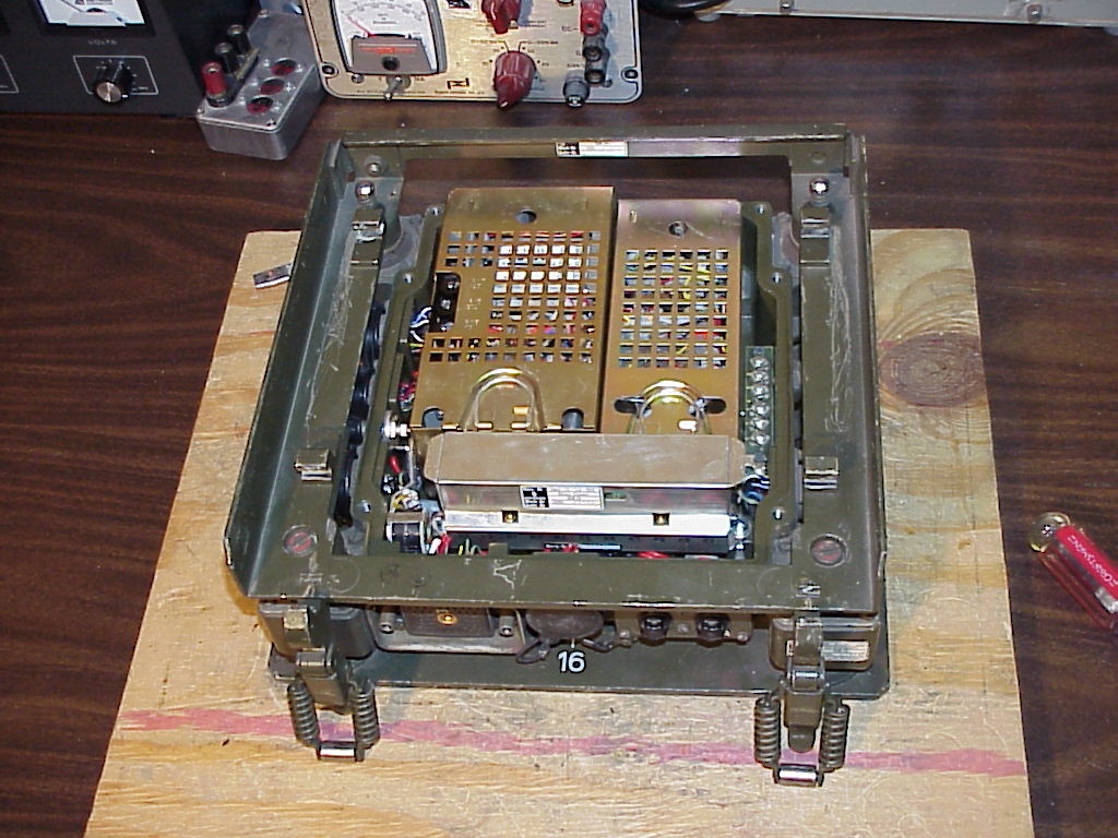
So far, I have only obtained a transceiver chassis, control box and mounting, so I cannot provide much information about the antenna, antenna tuning unit, power surge protector or other accessories at this time. The audio connections on the control box and main chassis are compatible with common 1950’s U.S. audio accessories such as the H-33/PT handset and LS-166/U loudspeaker. Pictures I have seen of the correct German audio accessories (well, actually photocopied photocopied photocopies…) suggest that the correct German handset (called an H-33G) appears virtually identical to its U.S. counterpart, and the correct loudspeaker has a case like a U.S. LS-7 loudspeaker with a mounting like a U.S. LS-166. The headset looks a lot like a U.S. H-63/U with an AN/GSA-6 control box. The antenna whip elements are called MS118AK, MS117A and MS116A, and look very similar to U.S. elements with similar names, and the antenna base looks a lot like the U.S. MP-65. The knobs on the control box look just like 1950’s U.S. knobs. I’m really surprised at the similarities between this set and comparable U.S. sets, in spite of the fact that they were designed and built in different countries.
I first learned of the existence of the SEM-25 when I saw a pile of them on the shelves in the famous back room of Murphy’s shop in late 1998. Although I had never been very interested in foreign military gear before, the SEM-25 looked like a neat radio, so I talked my folks into getting me one for Christmas in 1998. My dad and I made the hour-long drive down to Murphy’s shop on Christmas Eve, and I picked out the nicest-looking radio from the pile. It was even gift-wrapped in a stylish olive drab canvas cover!
At the time, Mike was charging $350 for the SEM-25, and $250 for a smaller but similar-looking radio which he called a “SEM-20”. The smaller radio is actually an EM-25 receiver; it’s basically a receive-only version of the SEM-25. It’s easy to get confused about the features and identification of these two radios, because they both use the same control box and share many modules, so the EM-25 is prone to have stickers which say “SEM-25” (or even “SEM-35”; it shares two internal modules with the SEM-35 backpack transceiver) on and inside it, and it will have controls for transmitting functions which it does not perform.
The “SEM” in “SEM-25” is short for “Sender-Empfangsgerät”, which is German for “transmitter-receiver”. Similarly, the “EM” in “EM-25” is short for “Empfangsgerät”, which is German for “receiver”.
Specifications
General
| Modes | Simplex, retransmit |
|---|---|
| Frequency range | 26.00-69.95 MHz |
| Channel spacing | 50 kHz |
| Number of channels | 880 |
| Channel selection | 44 1-MHz bands, 20 50-kHz channels each |
| Programmable channels | 10 |
| Modulation | FM |
| Operation, including frequency selection | Operated from a transceiver-mounted control box, or from a relocatable control box in vehicle (max. cable length 10m) |
| Transmitter operation |
|
| Remote input and output arrangement | From telephone remote control over field phone wires, up to 3 km long, max. resistance 480 ohms |
| Temperature range | Operating range from -45°C to +60°C |
| Overvoltage protector | For transients up to 65V from the battery regulator |
| Power supply | 24V battery supply, negative ground, permissible voltage range 21V to 29V, short term overvoltage up to 32V |
Transmitter
| Output power | High: 15 W Low: approx. 1 W |
|---|---|
| Calling frequency | 1600 Hz |
| Audio input |
|
| Warm-up time | approx. 30 seconds |
Receiver
| Sensitivity | <= 0.5 µV for 20 dB s/n with 1000 Hz modulation and 10.5 kHz deviation |
|---|---|
| Bandwidth | >= 30 kHz at 6 dB points |
| Selectivity | +/- 50 kHz at 80 dB points |
| Audio output |
|
Power Supply
| Voltage | 24V battery (21V to 29V), negative ground, permissible short term overvoltage up to 32V |
|---|---|
| Power requirements, RX | approx. 10 W |
| Power requirements, TX Low | approx. 50 W while transmitting |
| Power requirements, TX High | approx. 80 W while transmitting |
| Power requirements, TX Low or TX High | approx. 29 W when not transmitting |
Sizes and Weights
| Item | Height (mm) | Width (mm) | Depth (mm) | Weight (kg) |
|---|---|---|---|---|
| Control box | 174 | 228 | 75.5 | 2.54 |
| Transceiver | 222 | 268 | 255 | 14.59 |
| Transceiver mount | 120 | 320 | 300 | 9.43 |
| Receiver | 222 | 196 | 255 | 11.08 |
| Receiver mount | 120 | 320 | 230 | 6.68 |
| Antenna tuning unit | 122 | 290 | 110 | 3.70 |
| Overvoltage protector | 93 | 250 | 126 | 2.62 |
| Spares case | 48 | 140 | 140 | 0.73 |
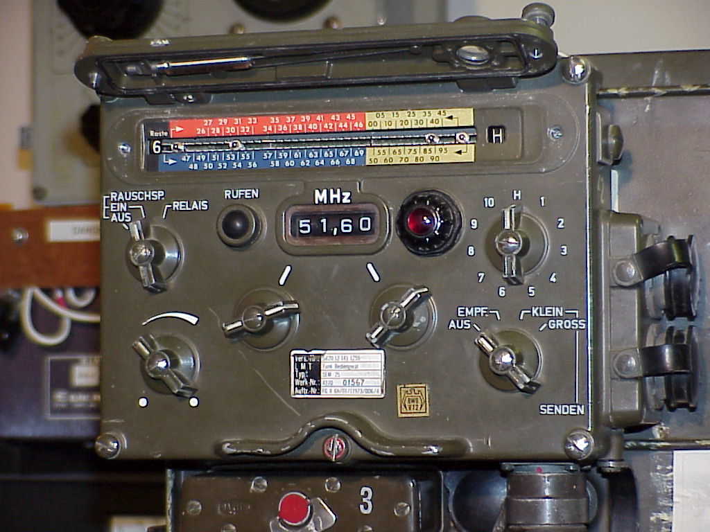
Controls
This section decribes the functions of the controls on the SEM-25 control box.
| Ref. | Description |
|---|---|
| A | Channel programming drum (behind cover) |
| B | Call button: Keys transmitter, sends 1600 Hz tone |
| C | Squelch |
| D | Volume |
| E | Manual tuning, 1 MHz steps |
| F | Manual tuning, 50 kHz steps |
| G | Power |
| H | Channel selector (H = manual tuning) |
| I | Power-on light (turn bezel to dim) |
Power Switch Settings (Ref. G)
| AUS: | Off |
|---|---|
| EMPF: | Receive-only |
| SENDEN KLEIN: | Transmit/receive (low power) |
| SENDEN GROSS: | Transmit/receive (high power) |
Squelch Switch Settings (Ref. C)
Note: Squelch is opened by carrier level, equivalent to “old” mode in U.S. radios.
| RAUSCHSP. AUS: | Squelch off |
|---|---|
| RAUSCHSP. EIN: | Squelch on |
| RELAIS: | Relay (retransmit) |
Connectors
This section describes the functions of the external connectors on the SEM-25.
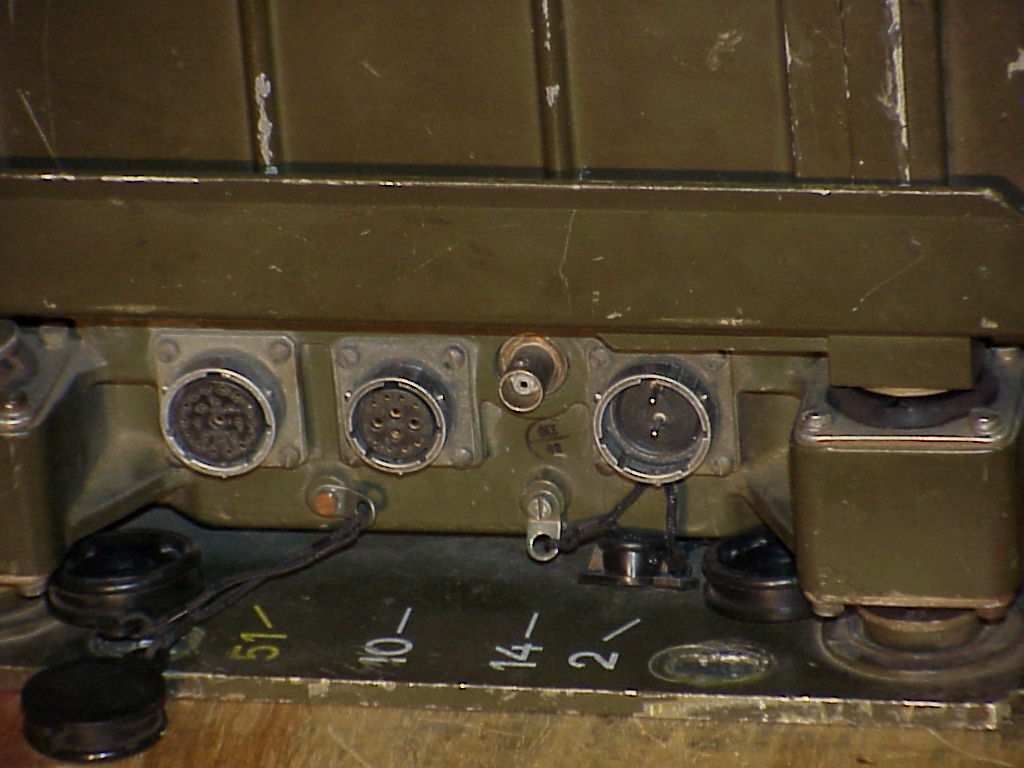
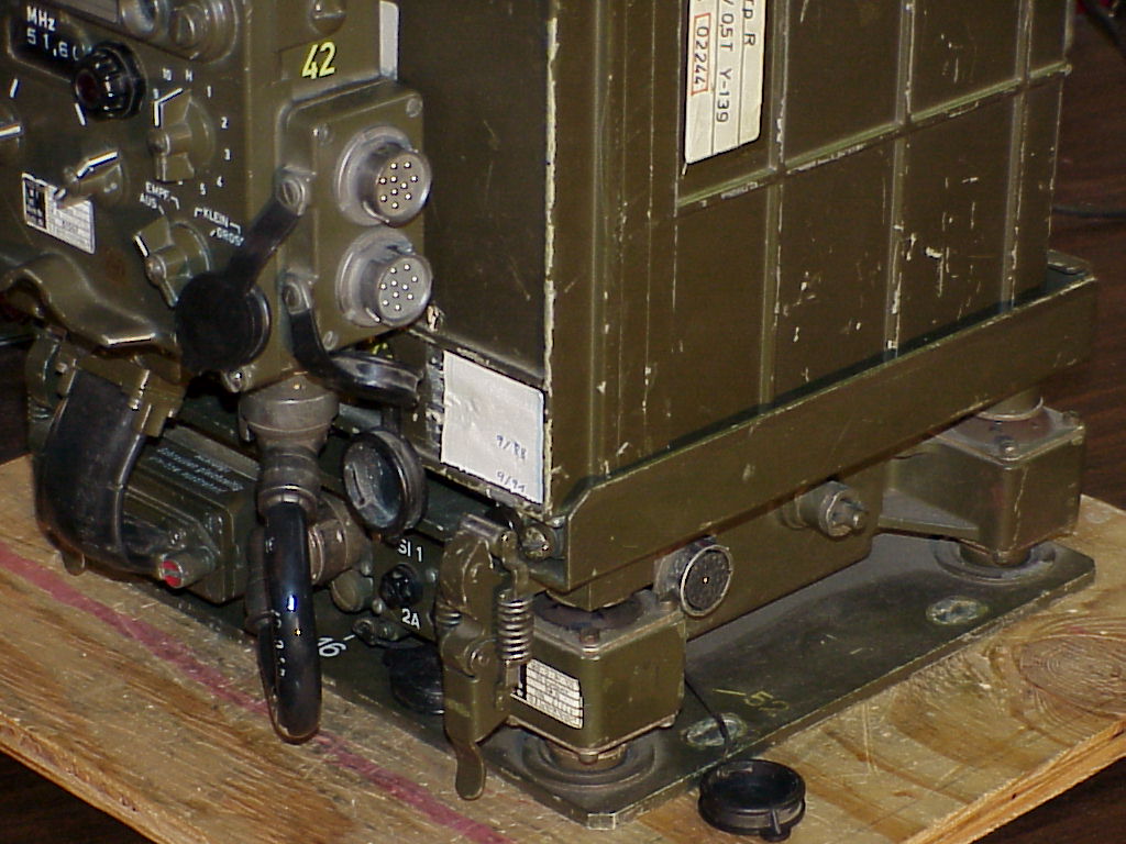
| Ref. | Description |
|---|---|
| J | From transceiver #1 in multi-radio sets |
| K | Antenna tuner control |
| L | Antenna RF |
| M | Power input |
| N | Mounting/transceiver interconnect |
| O | Audio |
| P | Control box/mounting interconnect |
| Q | Receiver fuse (2A) |
| R | Transmitter fuse (6.3A) |
| S | To transceiver #2 or aux. receiver in multi-radio sets |
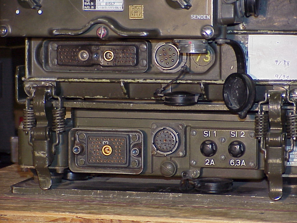
Modules
This section identifies the SEM-25’s major internal modules. Note that two of the modules (as noted below) are also used in the SEM-35 backpack/vehicular transceiver.
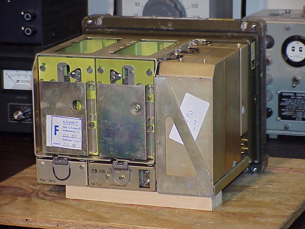
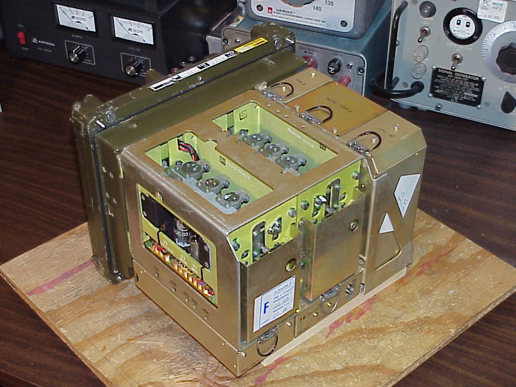
| Ref. | Description |
|---|---|
| N | Mounting/transceiver interconnect (external) |
| O | Audio connector (external) |
| P | Control box/mounting interconnect (external) |
| Q | Receiver fuse (2A) (external) |
| R | Transmitter fuse (6.3A) (external) |
| T | Transmitter RF |
| U | Receiver RF |
| V | Modulator amplifier, 1600 Hz tone generator, and 11.5 MHz discriminator for automatic frequency control (AFC) of transmitter |
| W | Audio amplifier |
| X | Receiver power supply and control amplifier |
| Y | Frequency synthesizer (also used in SEM-35) |
| Z | IF (Intermediate Frequency) module (also used in SEM-35) |
| AA | Plugs for test box |
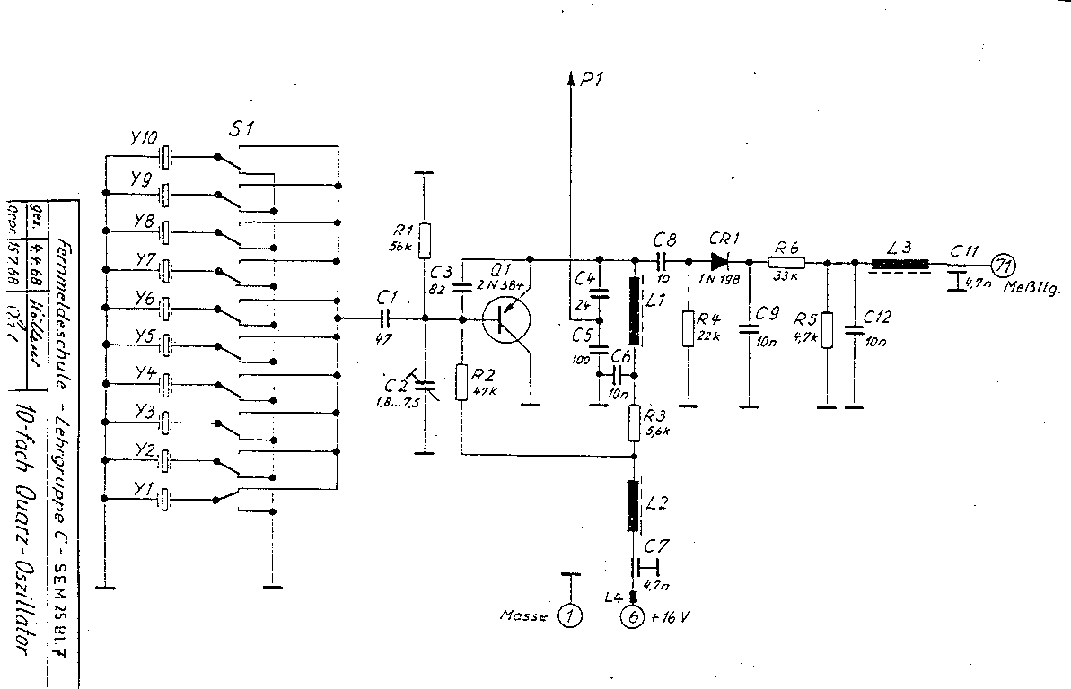
| BB | 10-frequency crystal oscillator |
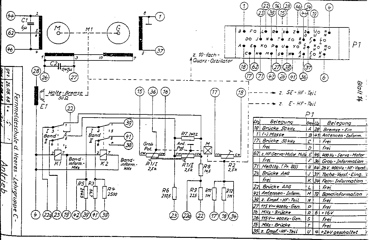
| CC | Receiver servo |
| DD | Transmitter servo |
| EE | Transmitter power supply |
| FF | Motor drive power supply for external antenna tuner |
| GG | Relays for interconnect of multiple transceivers |
| HH | 600 ohm balanced audio connections |
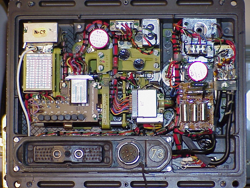
Internal Adjustments
While we have the case open, here are some of the major internal adjustments:
| Control | Label | Location | Function |
|---|---|---|---|
| R36 | Rauschperre | Audio amp. (Ref. W) | Squelch level |
| R5 | NF-Pegel | Audio amp. (Ref. W) | Audio level |
| R13 | Eing. | Mod. amp. (Ref. V) | Mod. amp. input gain |
| R26 | Ausg. | Mod. amp. (Ref. V) | Mod. amp. output gain |
| R38 | Tacho | Rx power supply (Ref. X) | Stepping speed trim (?) |
Schematics
The diagrams in this section were scanned at 150 pixels per inch, and you will probably need to use an external graphics-editing program to print them (simply clicking your browser’s “Print” button probably won’t work well).
The diagrams were all scanned from photocopied manuals, and the originals are just as blurry as the scans, so don’t bother asking for photocopies of the schematics! :-)
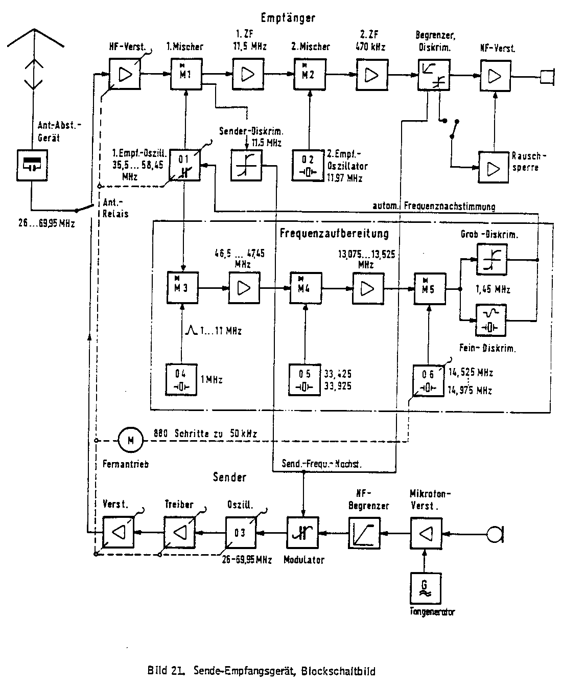
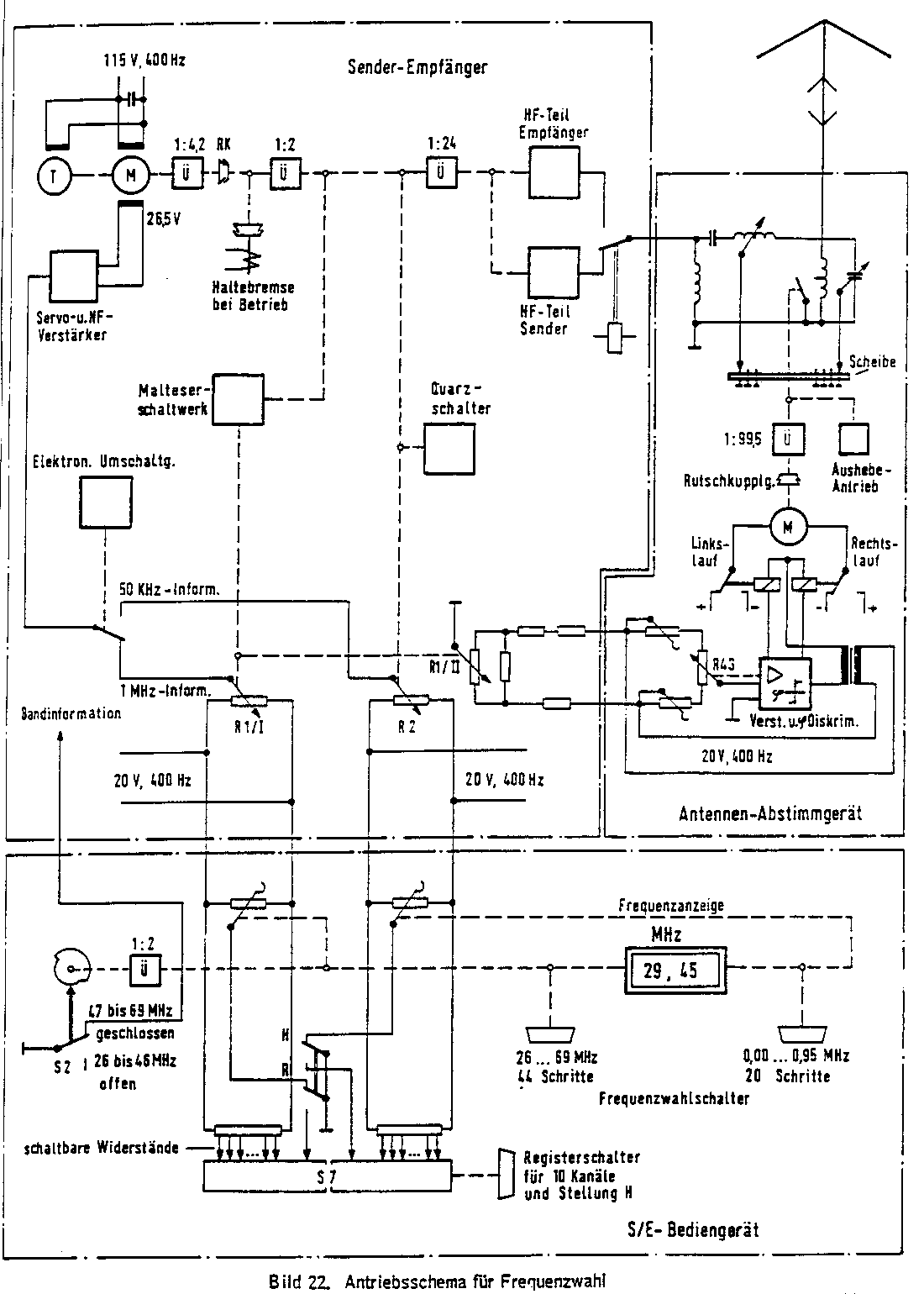
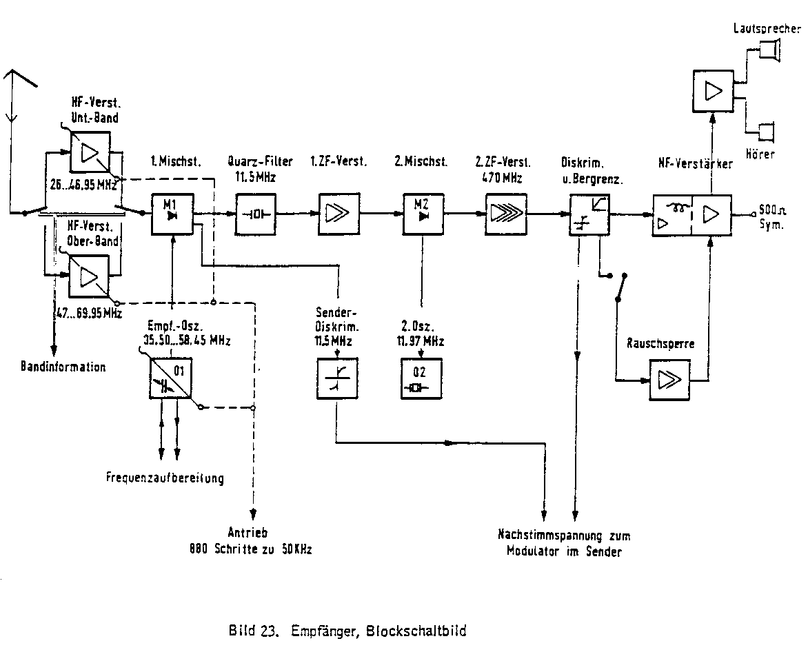
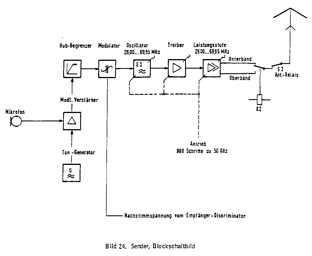
Block Diagrams
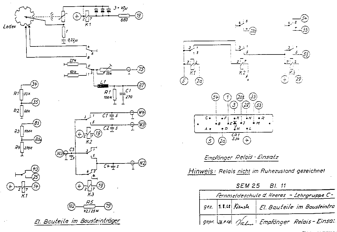
| Description | File | Size |
|---|---|---|
| Transceiver | blk01.gif | 1100×1338, 33k |
| Frequency selection | blk02.gif | 1100×1540, 44k |
| Receiver | blk03.gif | 1172×946, 20k |
| Transmitter | blk04.gif | 1082×888, 12k |
| Antenna tuner (external) | blk05.gif | 948×1240, 15k |
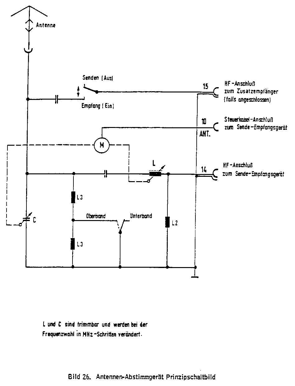
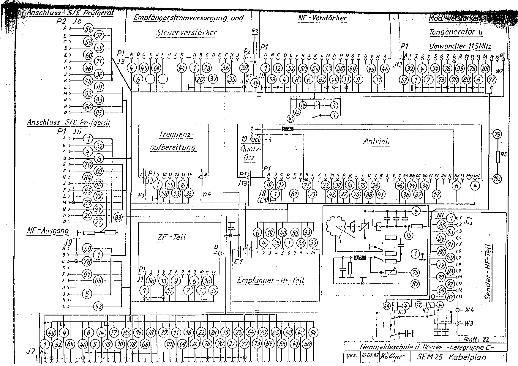
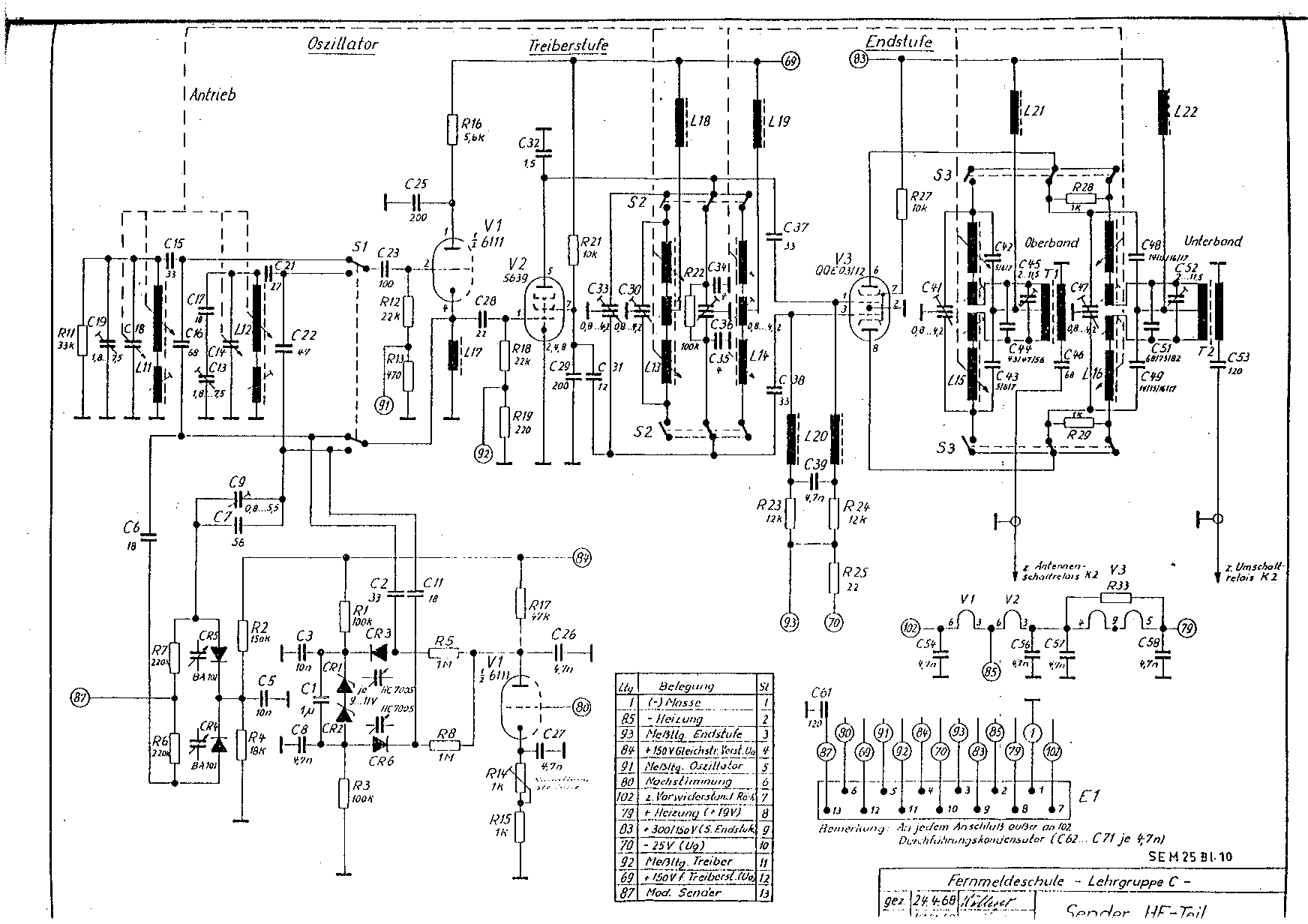
Schematic Diagrams
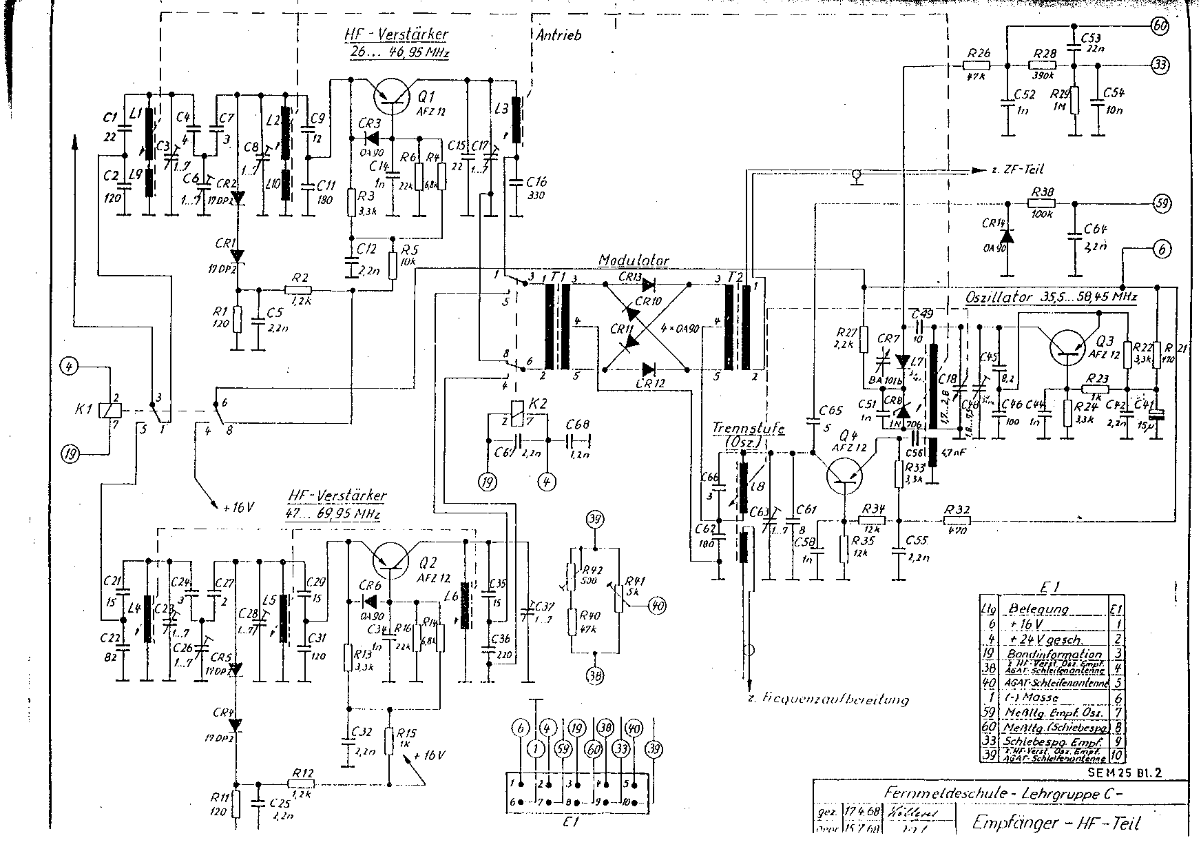
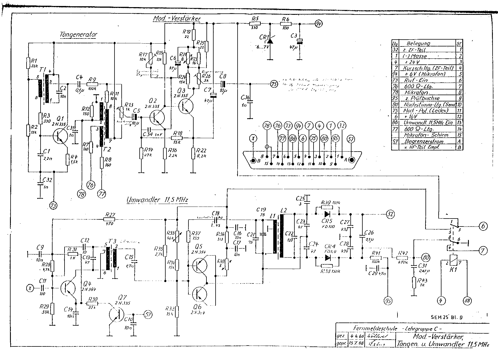
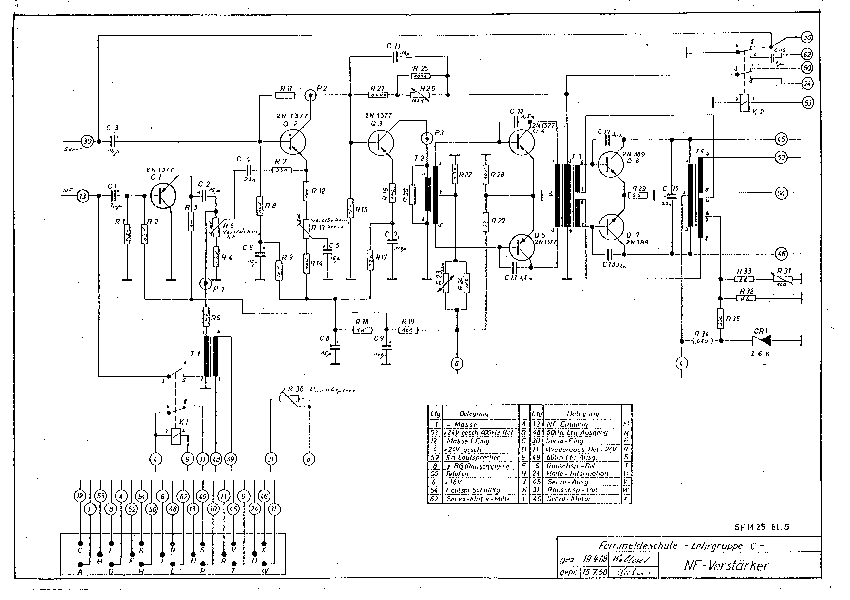
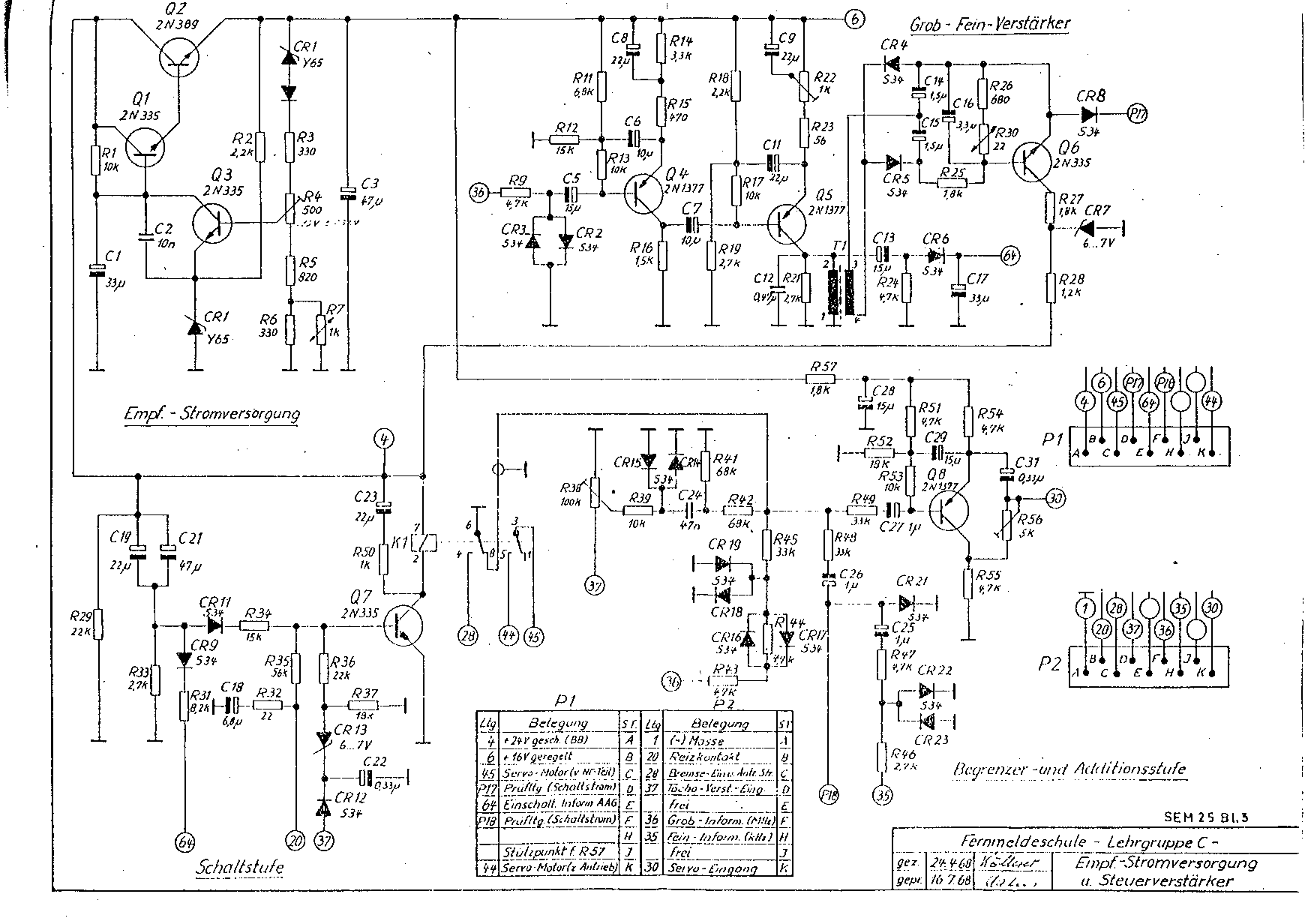
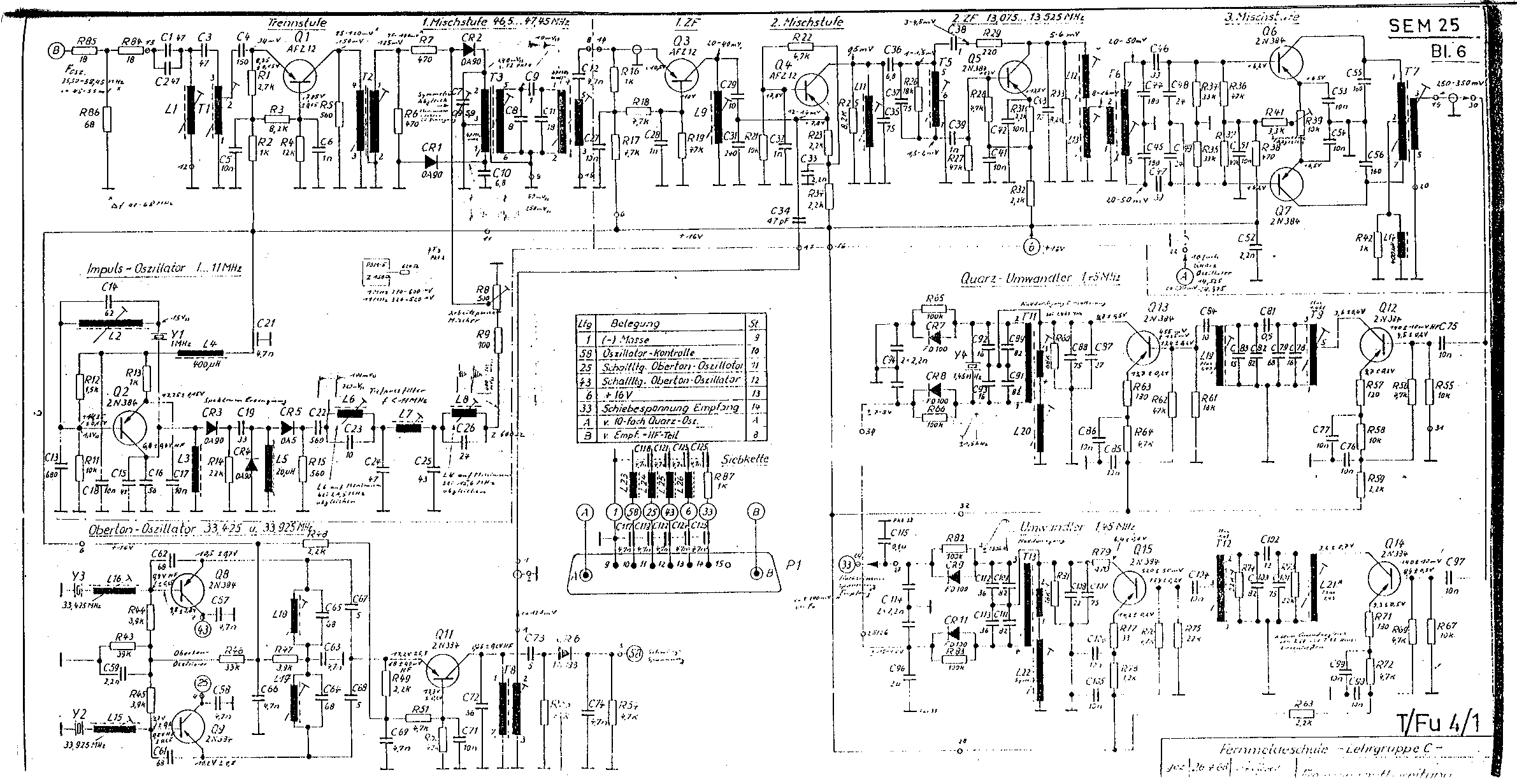
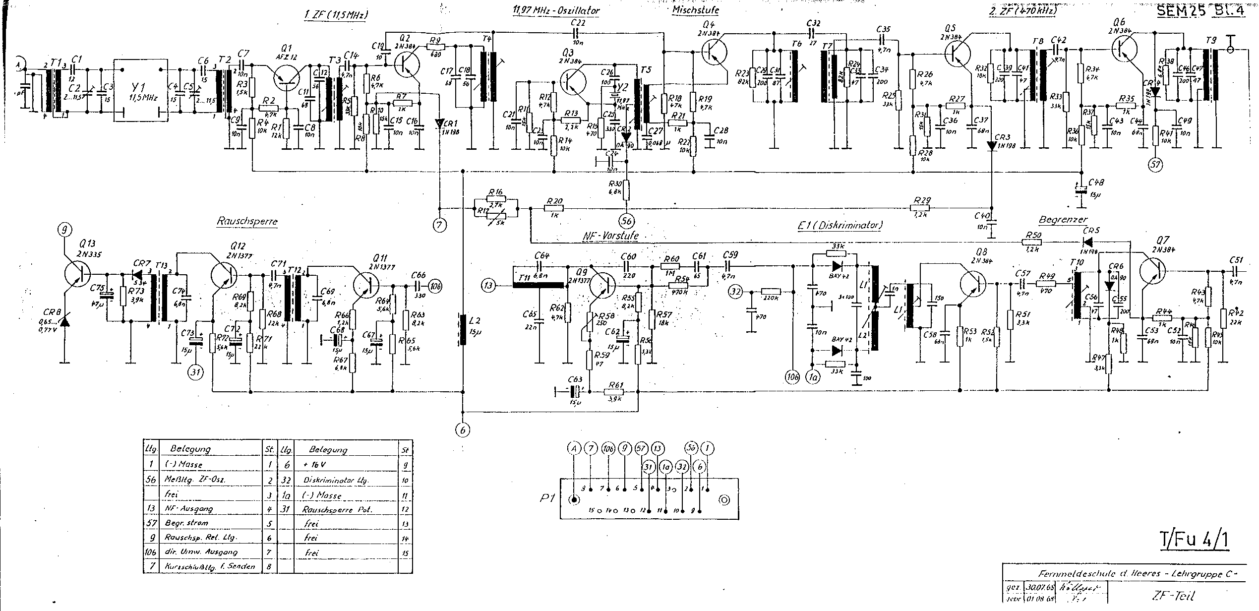
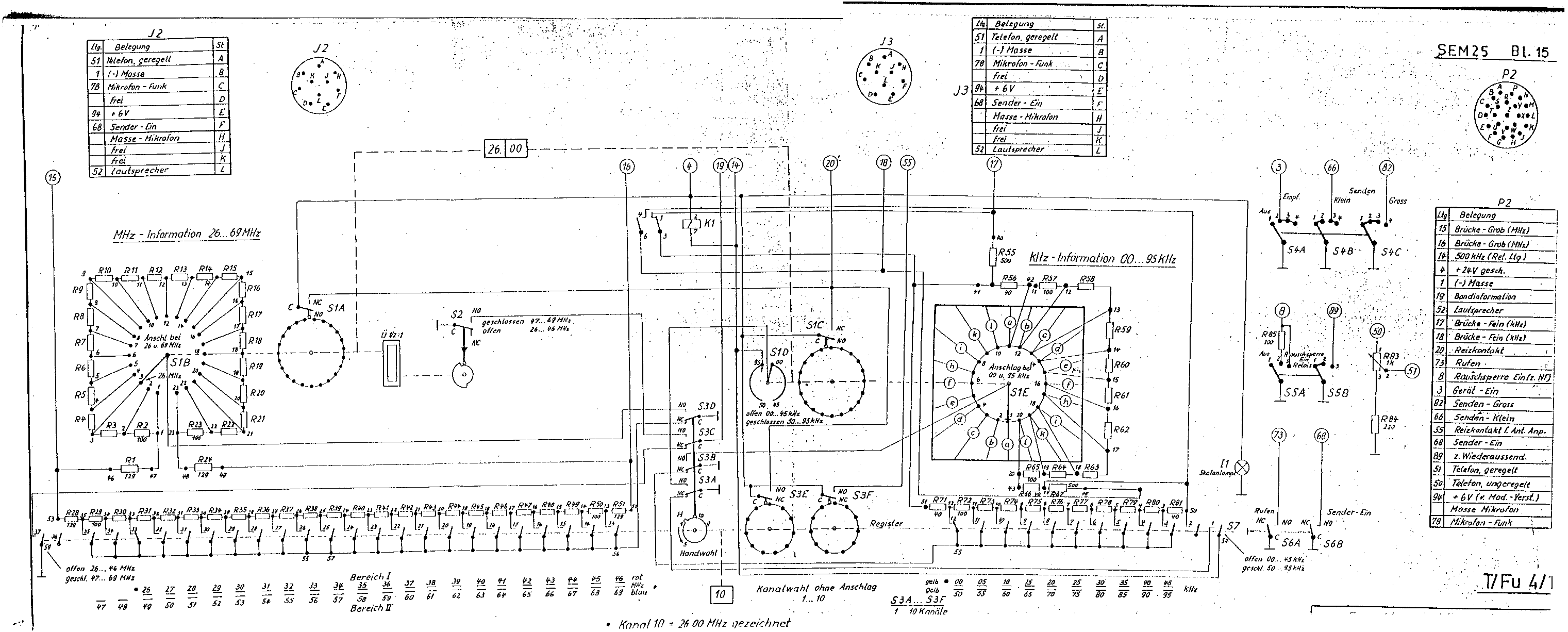
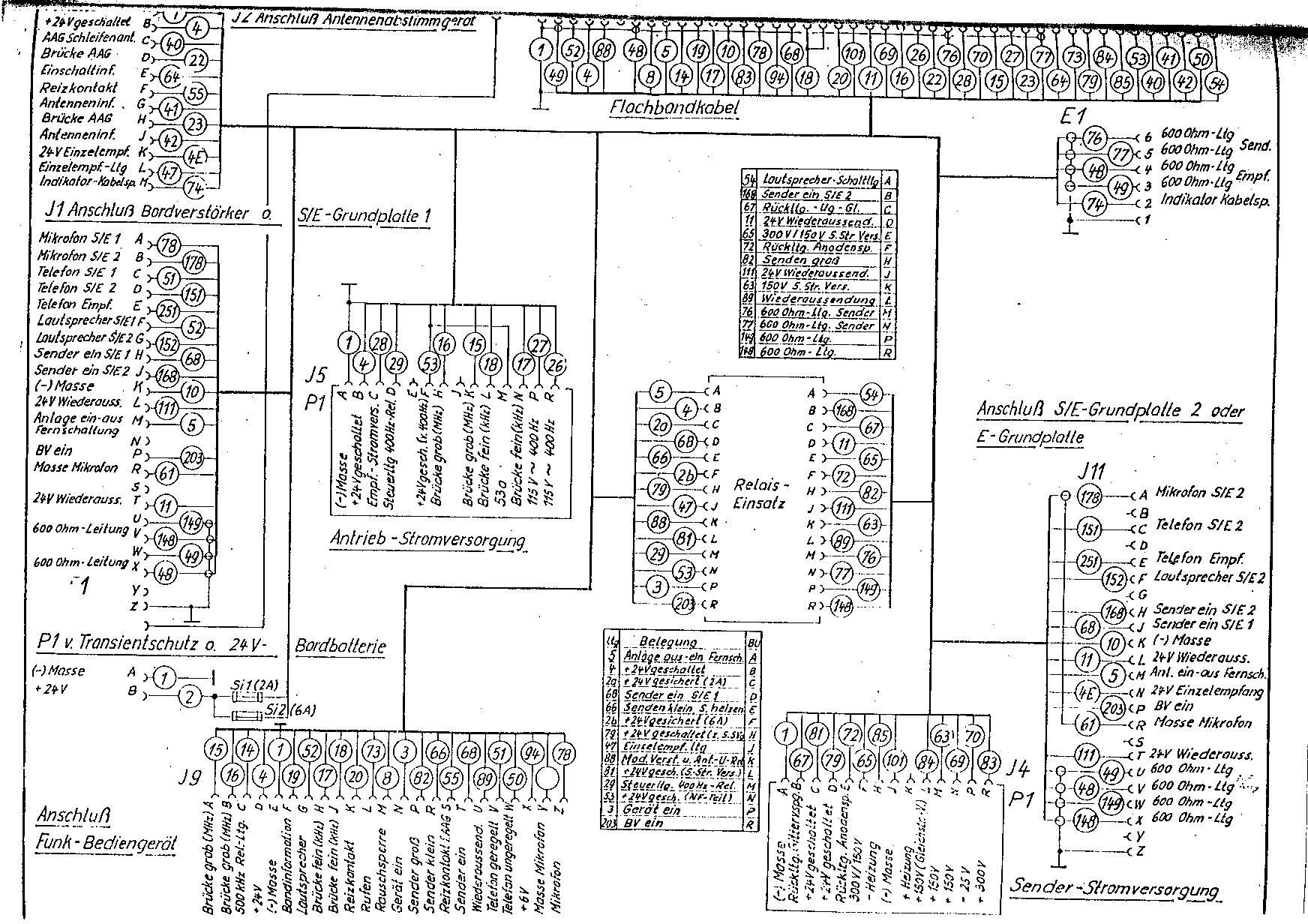
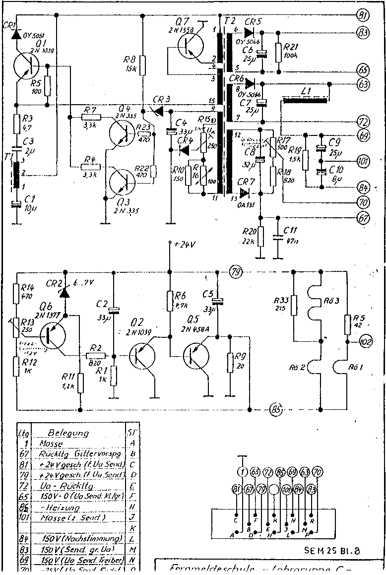
The “Ref.” column shows the corresponding reference letters from the module identification pictures (where applicable), to help you figure out which part of the radio is described by each schematic.
| Description | Ref. | File | Size |
|---|---|---|---|
| Wiring (main chassis) | — | sch01.gif | 1744×1232, 90k |
| Transmitter RF | T | sch02.gif | 1744×1232, 70k |
| Receiver RF | U | sch03.gif | 1744×1232, 70k |
| Modulator amplifier module | V | sch04.gif | 1744×1232, 62k |
| Audio amplifier module | W | sch05.gif | 1744×1232, 55k |
| Receiver power supply module | X | sch06.gif | 1744×1232, 66k |
| Frequency synthesizer module | Y | sch07.gif | 2381×1231, 117k |
| IF module | Z | sch08.gif | 2539×1232, 84k |
| 10-freq. crystal oscillator | BB | sch09.gif | 1193×768, 17k |
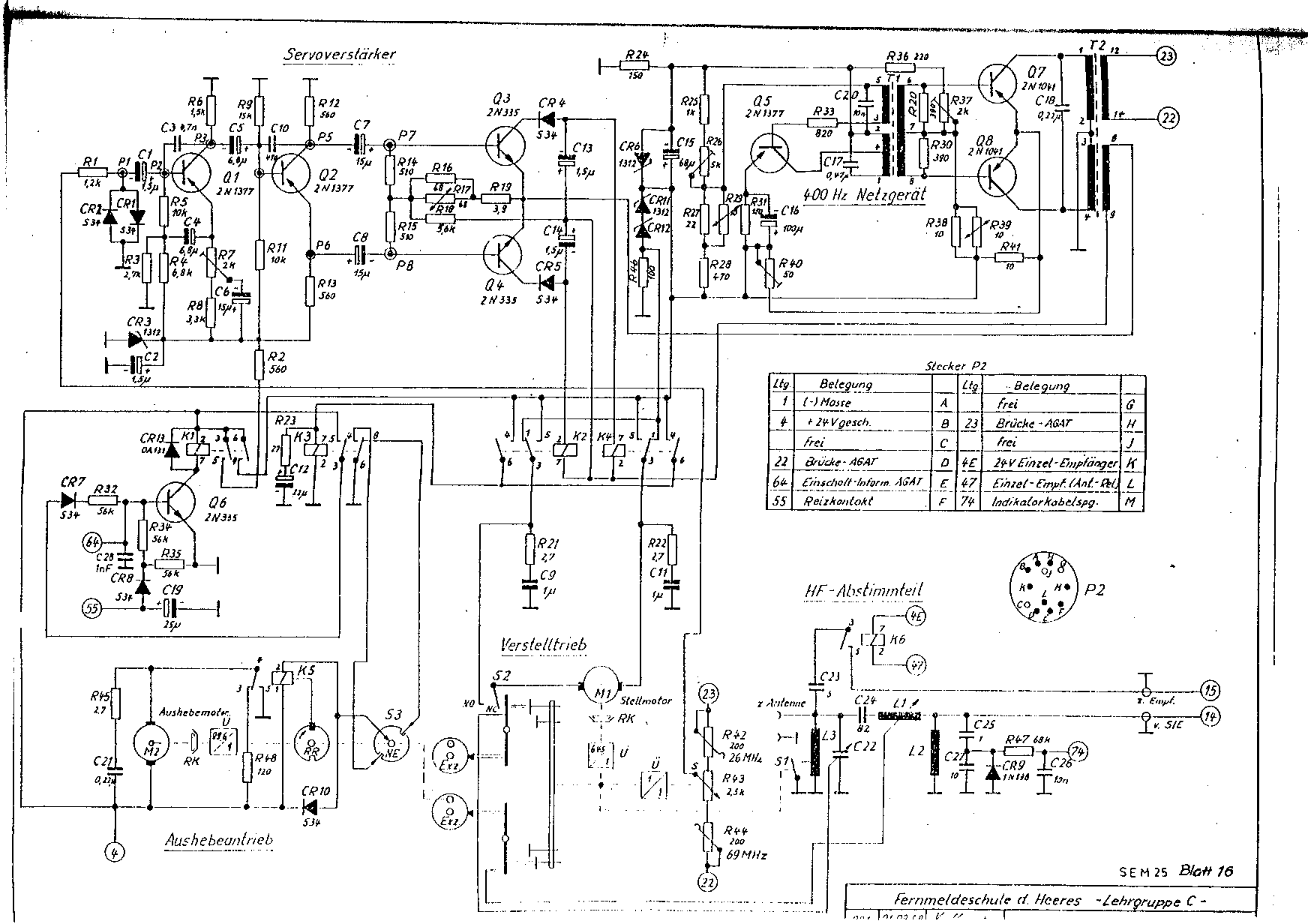
| Receiver servo | CC | sch10.gif | 1196×778, 38k |
| Transmitter servo | DD | sch11.gif | 1172×809, 19k |
| Control box | — | sch12.gif | 3042×1226, 104k |
| Wiring (mounting) | — | sch13.gif | 1744×1232, 94k |
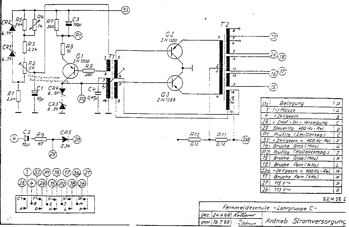
| Transmitter power supply | EE | sch14.gif | 778×1159, 36k |
| Motor drive power supply | FF | sch15.gif | 1187×772, 26k |
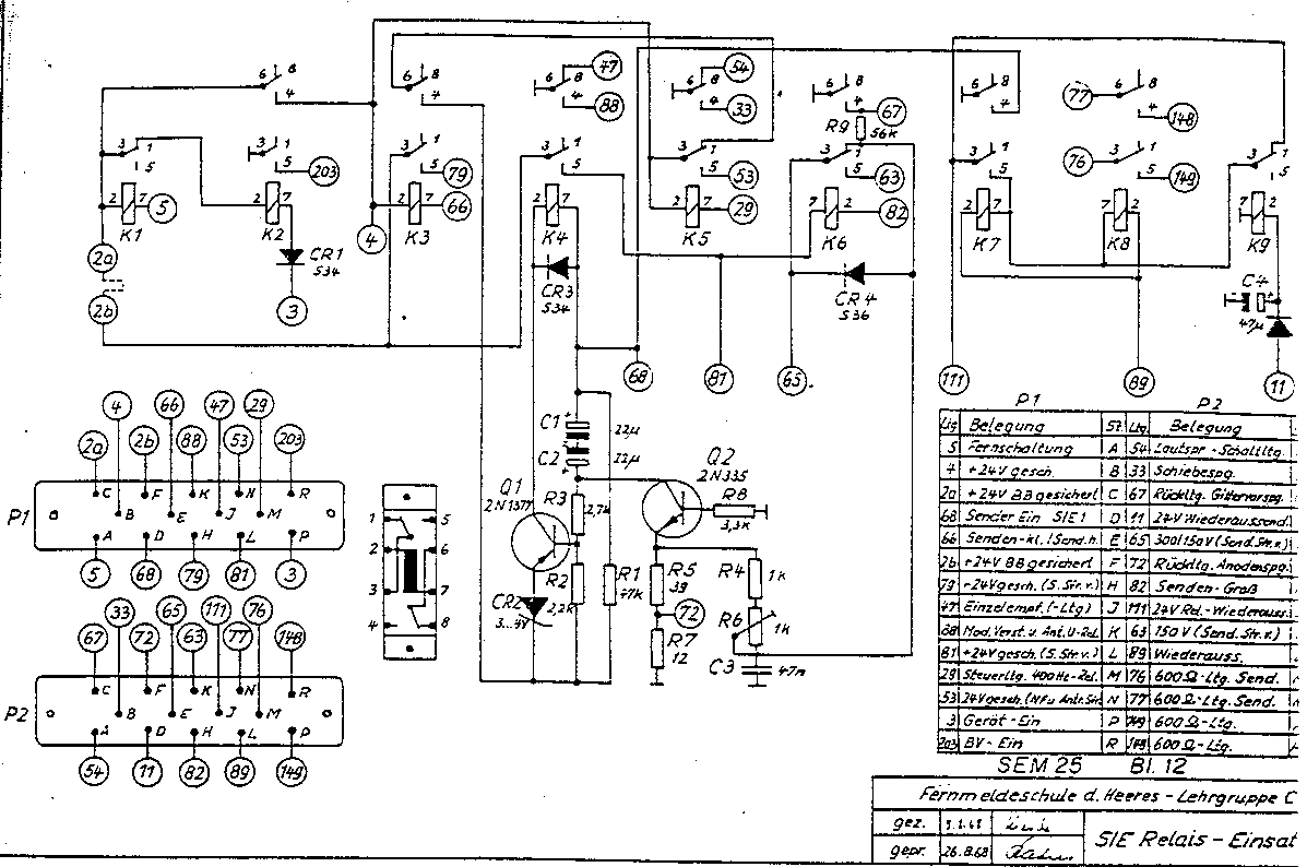
| Interconnect relays | GG | sch16.gif | 1197×794, 36k |
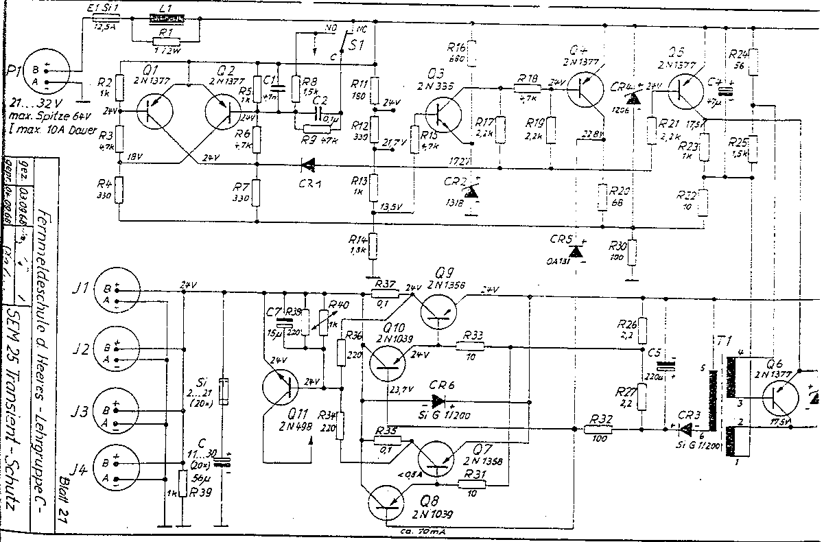
| Transient protector (external) | — | sch17.gif | 1201×790, 34k |
| Antenna tuner (external) | — | sch18.gif | 1744×1232, 68k |
English/German Translations
This section lists rough translations of some German words, phrases and abbreviations as used in the SEM-25’s schematics, module labels, etc. My command of German is very poor, so there may be mistakes here… please comment if you can correct any of my translations!
- Abstimmgerät
- Radio tuner (tune + apparatus)
- Abstimmteil
- Radio tuner section (tune + part)
- Additionsstufe
- Addition stage
- Anschluß
- Connection
- Antennen
- Antennas
- Antrieb
- Drive, driver, motor
- Ausgang
- Output
- Bausteinträger
- Component carrier
- Bauteile
- Components
- Bedien
- Control head
- Begrenzer
- Limiter
- Blockschaltbild
- Block diagram
- Bordbatterie
- On-board battery
- Bordverstärker
- Intercom (on-board + amplifier)
- Diskriminator
- Discriminator
- Eingang
- Input
- Einsatz
- Part, component
- Empf.
- Receive or receiver
- Empfänger
- Receiver
- Endstufe
- Output stage
- erdfrei
- Balanced (i.e. “balanced line”; literally, “ground-free”)
- Frequenzaufbereitung
- Frequency synthesizer
- Funk
- Radio
- geschlossen
- Closed
- gezeichnet
- Drawn
- gross
- Large
- Grundplatte
- Mounting (base + plate)
- HF
- Radio frequency (RF)
- Hinweis
- Note
- im
- In
- Kanalwahl
- Channel selection
- klein
- Small
- Leitung
- Line, wire
- Ltg.
- Line, wire
- Masse
- Common, ground
- Mischstufe
- Mixer
- Netzgerät
- Mains power adapter
- NF
- Audio frequency
- Oberton
- Overtone
- offen
- Open
- Oszillator
- Oscillator
- Prüfgerät
- Test meter
- quarz
- Quartz
- rauschperre
- Squelch (noise + stop)
- relais
- Relay, retransmit
- rufen
- Call
- ruhezustand
- Off-state
- senden
- Transmit
- Sender
- Transmitter
- Servoverstärker
- Servo amplifier
- Steuerverstärker
- Servo amplifier
- Stromversorgung
- Power supply
- Teil
- Part
- Transientschutz
- Transient protector
- Treibertufe
- Driver stage
- Trennstufe
- Divider stage
- Umwandler
- Converter
- Verstärker
- Amplifier
- Vorstufe
- Input stage
- ZF
- Intermediate frequency (IF)
Credits
This work would not have been possible without the generous assistance of the following people:
Pictures were taken with a Sony MVC-FD91 digital camera. Reference letters were added with Visio 4 on a Windows NT box; all other image editing was performed with xv and gimp on a Redhat Linux system.
Scanned documents were scanned with a Umax Astra 1220S scanner and the SANE software under Redhat Linux, and then edited with xv and gimp.
Hello Dimitris !
The cable #51 is only neccessary if you are operating 2 sets SEM 52 together (for example as a relay-station), the cable #10 connects the antenna-tuner-unit sem 25 (AGAT) to the transceiver sem 25. From time to time this cable #10 is available at http://www.helmut-singer.de and/or http://www.bw-schmitti.de .
73,
Klaus, DL4FCY
Many thanks Klaus,
I m looking for buying these cabkes.
Any help?
Good evening at All SEM25 fans.
My name is Giovanni and I have a SEM25 and a EM25 with a AGAT.
I need help from those who are more experienced than me.
I connect everything according to schema, the SEM engine works but the AGAT stays motionless.
Turning on the transmitter, the AGAT rotates in full scale and does not move anymore.
The transmitter works, verified with its ros-meter, and the loudspeaker on some frequencies receives signals.
I checked the connection cables with the tester and they are all working.
Can someone help me?
Thank you from Milano
Giovanni
Hi Giovanni !
When changing the kHz- frequency on the control-box only, then the frequency displayed on the AGAT will not change. If the frequency on the control-box is changed in MHz-steps, then the AGAT-Display should Change. If not, please check the cable #10 which connects the AGAT with the Transceiver-unit.
73,
Klaus, DL4FCY
Hi Klaus,
thanks for your answer.
Unfortunately, the AGAT does not change both the kHz and the MHz controls.
If you manually rotate the circular frequency scale in the AGAT by switching on the transmitter, the scale will rotate to full scale and stop.
I’ll check pin to pin cable # 10.
Greetings
Giovanni
Has anybody an idea on which frequencys transmittions is done usually.
I have an old Wollys Nekaf with a build on SEM 25 but I have idea on which frequentie to check. As I’m living in Belgium, I have neither an idea how far the transmittion will work and who I might contact, but it is just for fun. My sem25 should work, but I only hear some static.
Kind regards,, Erwin
Hi Erwin,
In Europe the amateur bands that can be used with SEM are:
10 meters (28,000 to 29,700 kHz);
6 meters (50,000 – 52,000 MHz) – also called 50 MHz band.
However, check the Belgium frequency plan and if you need some license.
73
Giovanni IW2BZO
Hi Klaus,
Thanks to your instructions I checked all the cables.
Cable no. 3 did not make good contact.
Disassembled, cleaned and reassembled, everything works perfectly.
Shortly, I set up the equipment on a MUNGA and I will try to calibrate the AGAT.
Thank you
73
Giovanni IW2BZO
Giovanni! When serving in the Norwegian army , I used the SEM-25. IF something did not work, we checked and cleaned the cables. Especially earth-conections were checked (Bad climate). After that, everything was ok. Once a Leopard 1a was drowned in a bog. After 48hours, the tank was saved and the cleaning-work started. I remember that the radios (SEM-25 X2) still worked flawlessly!!!!
Hi Giovanni !
Thanks for the info !!! For the alignment of the AGAT you need special tools which are included to the Antenna check Box (in German: Antennen-Prüfgerät). Without them it will be very difficult to adjust the “C” and the “L”-Pins.
73,
Klaus, DL4FCY
Hi Klaus,
I have the tool, but I have no instructions.
I assume that for each step I have to act on the adjusting screws, until you get the lowest reflection.
Then, hope that there is someone listening…………
73
Giovanni IW2BZO
Ciao Giovanni !
Here are the instructions: Connect the antenna testing instrument or a swr-meter between SEM 25 and AGAT. Select the frequency you want to tune on the control-box of the transceiver. In the display of the AGAT the frequency (MHz) should be the same (for example: selected Frequency on the control-box SEM 25: 29,60 MHz., displayed frequency on the AGAT-display: 29 MHz). Then press the PTT an read the swr. If it is to high, open the 2 screws which are marked “L” and “C”. For ever MHz-Position there are 1 Aligning Pin “L” (= inductance tuning) and 1 Alingning Pin “C” (= Capacitance Tuning). Now hold the PTT pressed and insert the aligning tools in both holes and turn the tools alternating until the swr is low (or the reflected power has reached a minimum). This procedure must be repeated in every MHz-position you like to work. When I was in the Army many years ago, this was a job for a complete day… 26-69 MHz are 43 positions…
I hope I could help you.
73,
Klaus, DL4FCY
Thanks Klaus for the information.
I think I will have to take it very calmly and patiently!
At the end, also I put in the EM25 function to check if the SEM transmits ……. and I’ll let you know.
73
Giovanni IW2BZO
Hi Giovanni !
I’m looking forward for your informations !
I don’t know on which frequencies you want to use the sem 25, but I think on 10m. There are only a low number of channels which can be used. If the conditions are good, you will receive some stations on 29,50 or 29,60 MHz. I use my SEM 25 on these frequencies as a monitor – if there are stations, the condx are good, so it makes sense to look for other stations on 10m on the ssb or cw-segments as well as FM. I use a indoor antenna for 10m with my SEM 25 with a manual Tuner (YAESU FC-700), so the tuning procedure is much easier and quicker than with the AGAT.
73,
Klaus, DL4FCY
Hi Klaus,
thanks for the information.
73
Giovanni, IW2BZO
Hello, I have two sem25 and two sem35, one with its base for vehicle!
I also have the antenna base with its box coupling but I no longer have antenna strands MS116, MS117, MS118. Can you tell me where to get them?
thank you
Baudouin
ON2BJ
Hello Baudouin !
Please refer http://www.helmut-singer.de and/or http://www.bw-schmitti.de
From time to time they’re offering these parts.
73,
Klaus, DL4FCY