For a long time, I’ve had a passing interest in radar antennas. Not so much the antennas themselves, but mostly their azimuth-elevation (az-el) drives. Every now and then, I’d search on eBay for any such az-el drives that looked both interesting and inexpensive, with or without antennas. I finally found one to buy about a month ago, and here’s a little bit about it.
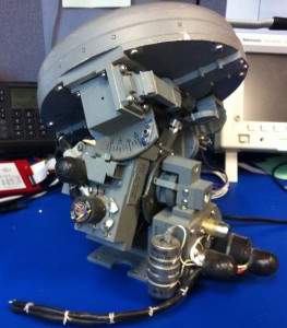
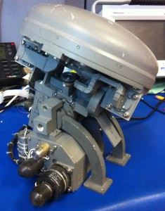
The eBay listing informed me that this antenna was originally part of a terrain-following radar system on the F-111 “Aardvark” aircraft. Some Googling informed me that it most likely belonged to the AN/APQ-171 system, which used two of these antennas mounted side by side in the nose of the aircraft, underneath the larger antenna of the AN/APQ-169 attack radar. Google showed me various pages with pictures of the antennas in the nose of an F-111, and the AN/APQ-171 system by itself in a promotional photo.
Jane’s describes the AN/APQ-171 this way:
The AN/APQ-171 is a dual-channel forward-looking multimode radar developed for the F-111. The radar’s primary function is to provide proper commands to control the F-111 automatically at a preselected set clearance height above the terrain.
Various other sources indicated that the system was developed by Texas Instruments, and was part of an upgrade applied to extend the useful life of the aging F-111 fleet both in the US and abroad. Australia was the last user of the F-111, finally retiring them in December of 2010.
The antenna that I received was mostly in good condition, but the azimuth drive had a sheared roll pin where one of its gears was attached to its shaft. I think it’ll be repairable, but this was one of the reasons that I went back to eBay and bought another one! It turned out that the seller had two more antennas left, which he listed at the same time. Another buyer and I each bid on one of them, and got them for the opening bid prices. The second antenna has both drives intact, but has some damage to the fiberglass radome.
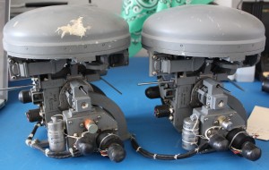
The elevation drive can traverse from about 35° below horizontal to about 15° above horizontal. The azimuth drive traverses about ±45° from straight ahead. Each axis can be locked at 0° by inserting a 1/8″ diameter pin, and I’ve locked both axes with pieces of drill rod in some of the pictures. The locking holes appear to be lined with tool steel bushings, leading me to believe that these holes are meant to be used with precision-ground tooling pins for alignment purposes rather than simple “remove before flight” locks.
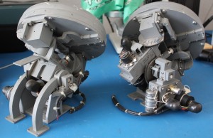
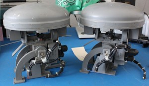
The antenna itself is a “flat plate antenna”, consisting of a number of slotted waveguide antennas arranged side by side in order to form the desired beam. It is covered by a fiberglass radome which includes both dielectric and conductive structures which I assume play some role in beam-forming.
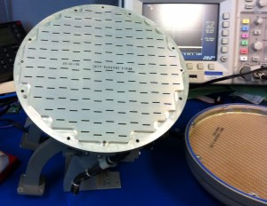
The antenna array is fed by two waveguides which are terminated with WR62 flanges, suggesting that the antenna is tuned somewhere in the 11.9 to 18.0 GHz range. The waveguide flanges lie in the same plane as the az-el drive’s mounting plate, and the waveguides are routed to the antenna through four rotary joints and many bends.
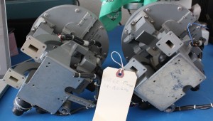
One of these days, I’d like to figure out how to run the drives from a microcontroller. I don’t expect to use them as functioning radar antennas, but I’d like to make a display with moving parts. If the antennas were usable on a ham radio band then I could come up with an excuse to use them somehow, but they appear to be designed for operation around 15 GHz, not overlapping any nearby microwave ham radio bands. Until then, they look nice sitting around and gathering dust.
I got one of these too, and fom what I remember,
the transcoils are three phase 24 volt drives for quick responce, and I think there is a position pot, and on the other axis a position and velocity(?) sensor, which from what I remember a long time ago is clasic position feedback loop design.
the same guy was selling the front end that attached to this unit, it has a YIG osc, unfortunatly there are about 5 boards of logic to dig around in (yuck), however the IF is enclosed b itself , is dual channel, and not to many IOs, so It could be fired up on its own. I got the YIG OSC pinout identified except for 2 wires (drat) And there is one missing part in the plumbing about 1 inch long on both sides. So it is close to firing it up, without the pulse processing. Transcoil is still around. THe phased array is nice, milled out of a block of Al.
you can run the drives from a computer, just classis motion control,
the not so hard part is converting a single drive signal into a three phase drive signal. (micro could do that too)
Not sure about the end stops though for each axis, and how that was controlled.
Nice unit for sure, I sweped it out and it liked 15 a lot, good responce over the band.
there is a writeup somewhere on flying the F111 using this set, at 200 feet near 800 mph, incredable
The azimuth axis has a brake that releases when 24V is applied, and the brake is also easy to remove temporarily. The elevation drive doesn’t appear to have a brake.
The shape of the drive motors suggests to me that they have a sensor mounted on the same shaft. It might be a tachometer generator to give angular velocity feedback; that’s just a guess from counting the number of cylindrical components geared into the drivetrains, and noting that the axis drives on my CNC milling machine each have a drive motor, tachometer generator for angular velocity feedback, and optical encoder for angular position feedback. Thus, it’s not unusual to have a dedicated sensor for velocity feedback rather than taking the derivative of the positional feedback input.
I don’t see any sort limit sensors, and the pin holes for locking the axes in the center position appear to have precision-ground bushings. From this I guess that the full system is calibrated for the 0-degree positions while pinned in place, and the axis limits might be entirely “soft”. 1/8″ minus-tolerance drill rod fits snugly in the axis locking pin holes.
Brings back memories.I was in the air force from 76′-80,stationed at Eglin AFB Forida.We supported air craft that were used to test weapon systems,including a FB-111.I have a picture I’d like to send you a photo.I know you’ll appreciate it.A B-47 landed there that had the nose of a F-111,used for tests of avionics for the General Dynamics FB-111
Thanks! I’d like to see that photo.
I was a Avionics Navigation Systems Specialist at the time,stationed at Eglin AFB Florida in 1977.I still have a picture or two,including a slide of one of the wheel wells.It had just been dropped off to be added to Eglin AFB Armament Museum a later date.The F-111 radome caught eye right off