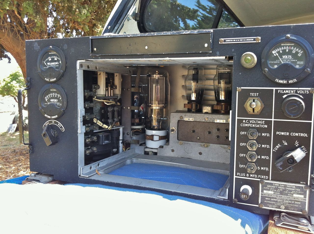
Westinghouse GP-7 Transmitter
I recently bought a Westinghouse GP-7 transmitter in the swap meet at this year’s annual West Coast Military Radio Collectors Group meeting, held in San Luis Obispo, CA at the beginning of May. This transmitter was made for use in Navy aircraft, and it requires 120 VAC 800 Hz power like other Navy radios of its era. Aircraft commonly use AC power at higher frequencies than our common 60 Hz “wall power” so that their transformers and motors can be lighter. The higher power frequencies allow transformers and motors to use less massive iron cores without magnetic saturation. 400 Hz power is now commonly used in large aircraft that require AC power supplies, but this transmitter was made before 400 Hz power became the standard. Unfortunately, it can’t simply be plugged into 60 Hz power. That would saturate the transformer cores, and then they would release their magic smoke and stop working.
The GP-7 was originally powered by a model 800-1 rotary inverter. Those are a bit hard to find, and they can easily be mistaken for mechanical sirens. There are lots of possible ways for a collector to power 800 Hz Navy radios:
- Use an original 800-1 inverter. Their cooling fans are very loud, though. They look just like mechanical sirens, and I’m told that they sound like them, too.
- Use a motor-generator. Paul Thekan N6FEG picked up such a motor-generator at the MRCG meet. It’s a really big unit. I’m told that it’s also very loud, but from magnetostrictive effects rather than blower noise. He plans to build a noise-insulating housing around it.
- Use a variable-frequency AC bench power supply. This is a nice way to provide 800 Hz AC power, but these supplies can be expensive.
- Some folks suggest trying a variable-frequency motor drive. I haven’t found one with the right specifications yet, though.
- Another collector has reported successfully modifying uninterruptible power supply (UPS) units that he bought inexpensively at swap meets.
- Last of all, the approach that I have settled upon: Modifying a solid-state power inverter to output 800 Hz instead of 60 Hz.
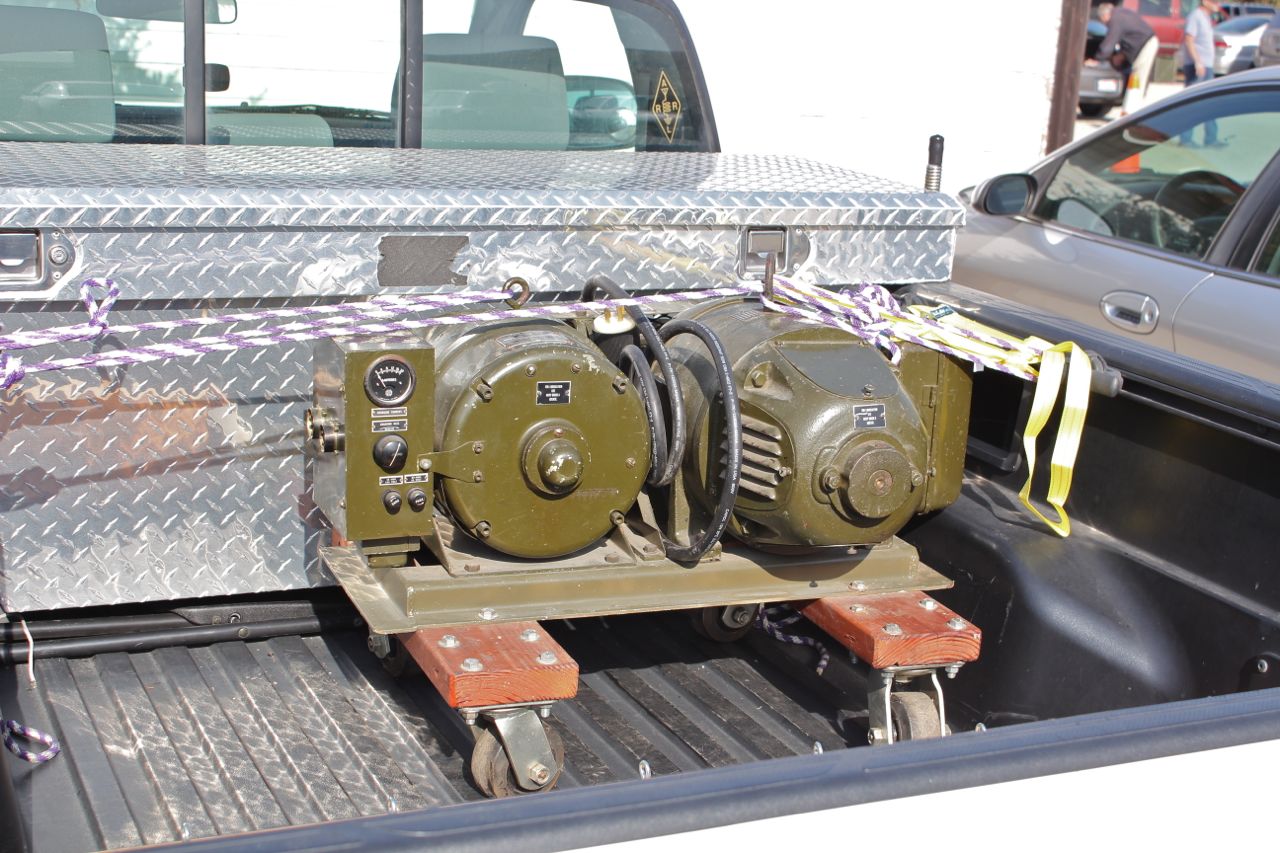
800 Hz Motor-Generator
I picked out a likely-looking “true sine wave output” inverter on Amazon.com, and ordered it. I selected a 24VDC input model because the current draw at 12V would have been too much for my 12V radio room supply with the GP-7 drawing its rated 8A at 120VAC 800 Hz. My PP-4763A power supply should feed it just fine, though.
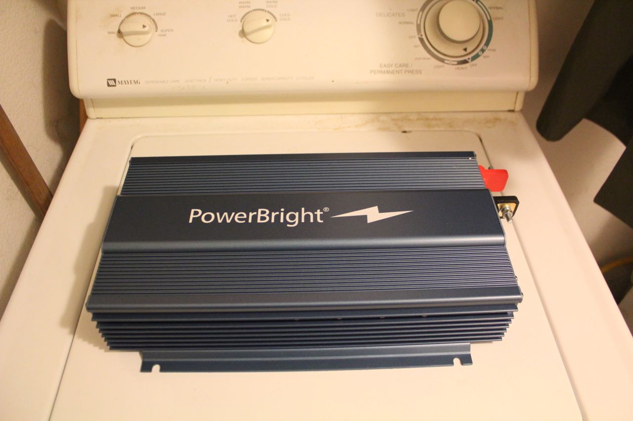
The one I selected is a Power Bright model APS-1000-24V. It arrived yesterday, and I unboxed it and made sure it worked before voiding its warranty by opening it up.
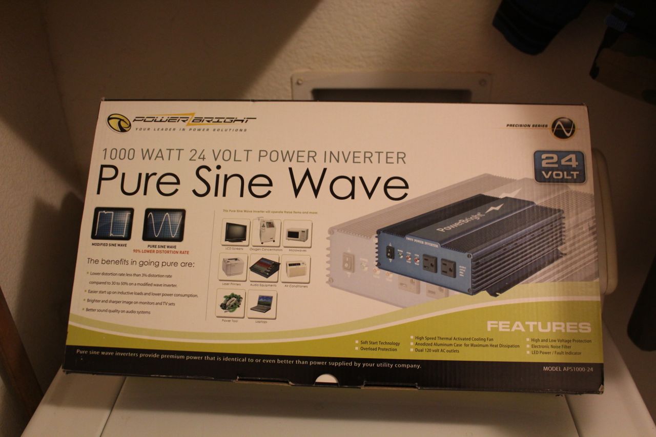
Inverter Just Arrived from Amazon
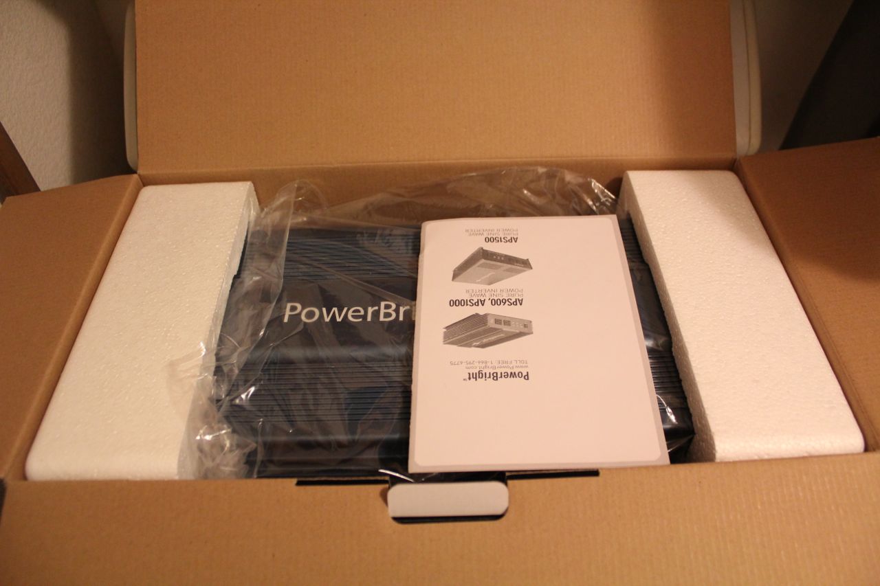
Unboxing Begins
Top Side of Inverter
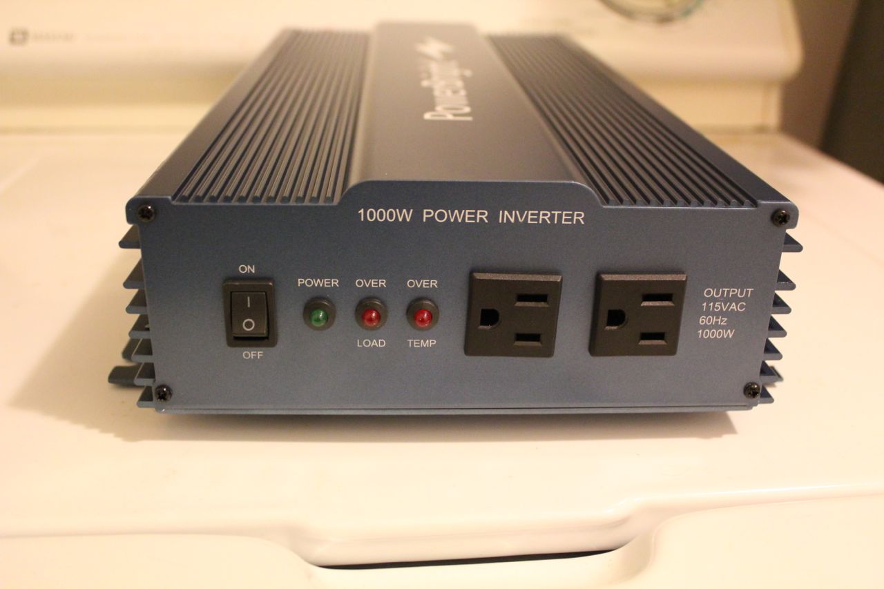
Front Panel of Inverter
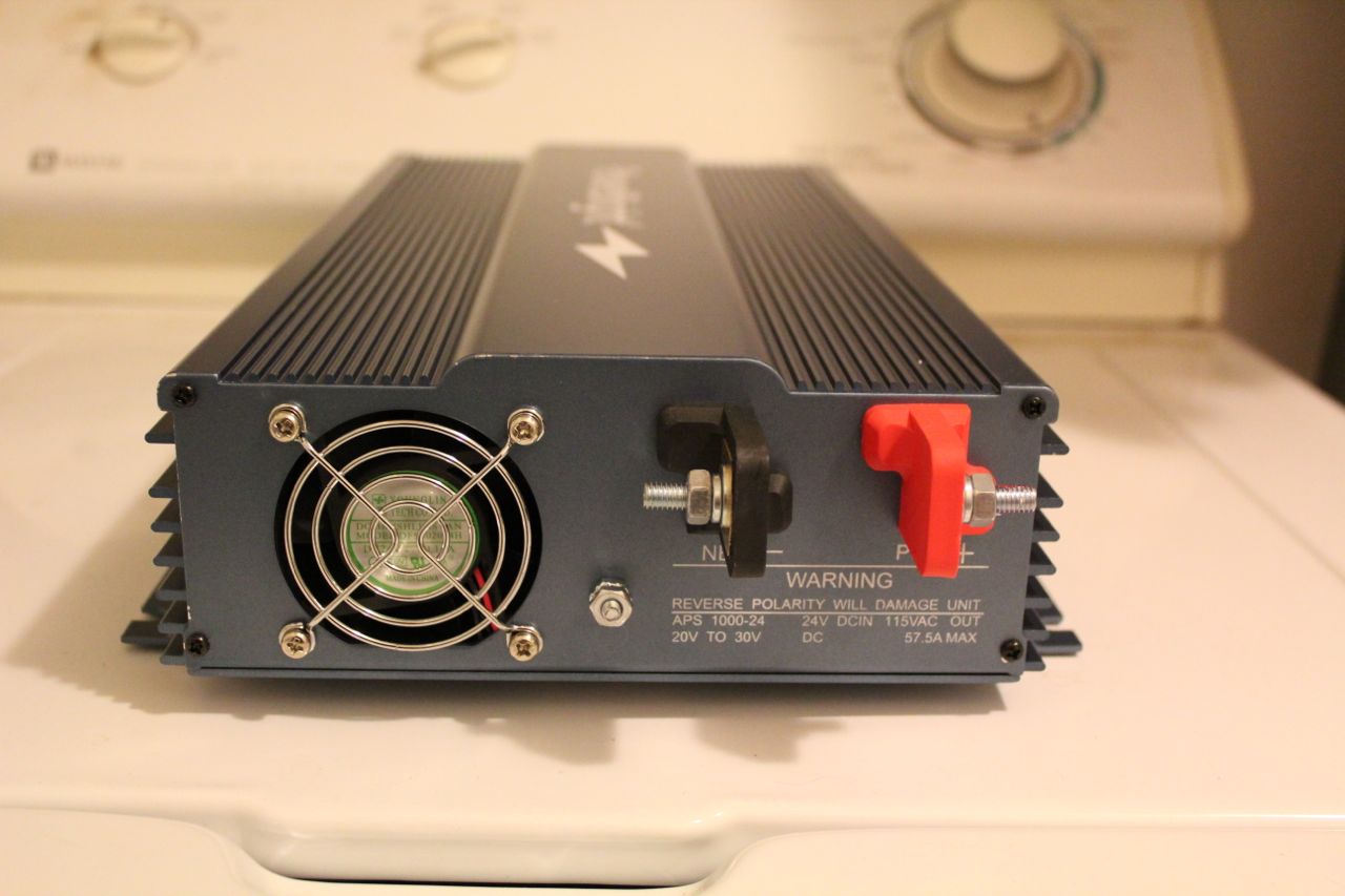
Rear Panel of Inverter
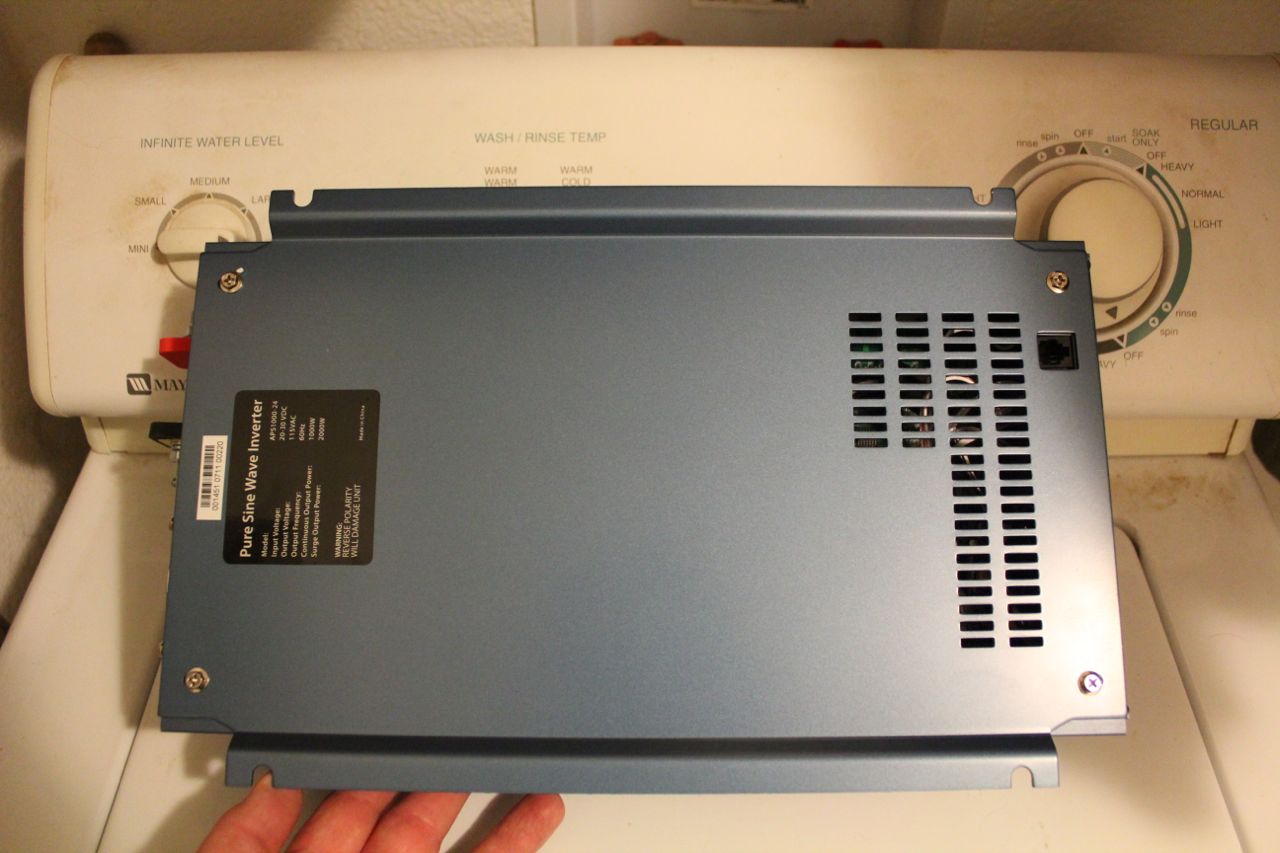
Bottom of Inverter
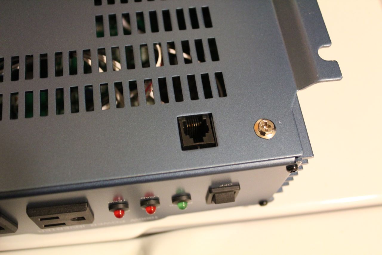
Remote-Control Port
Once I verified that I wouldn’t be returning it immediately under warranty, I immediately voided the warranty.
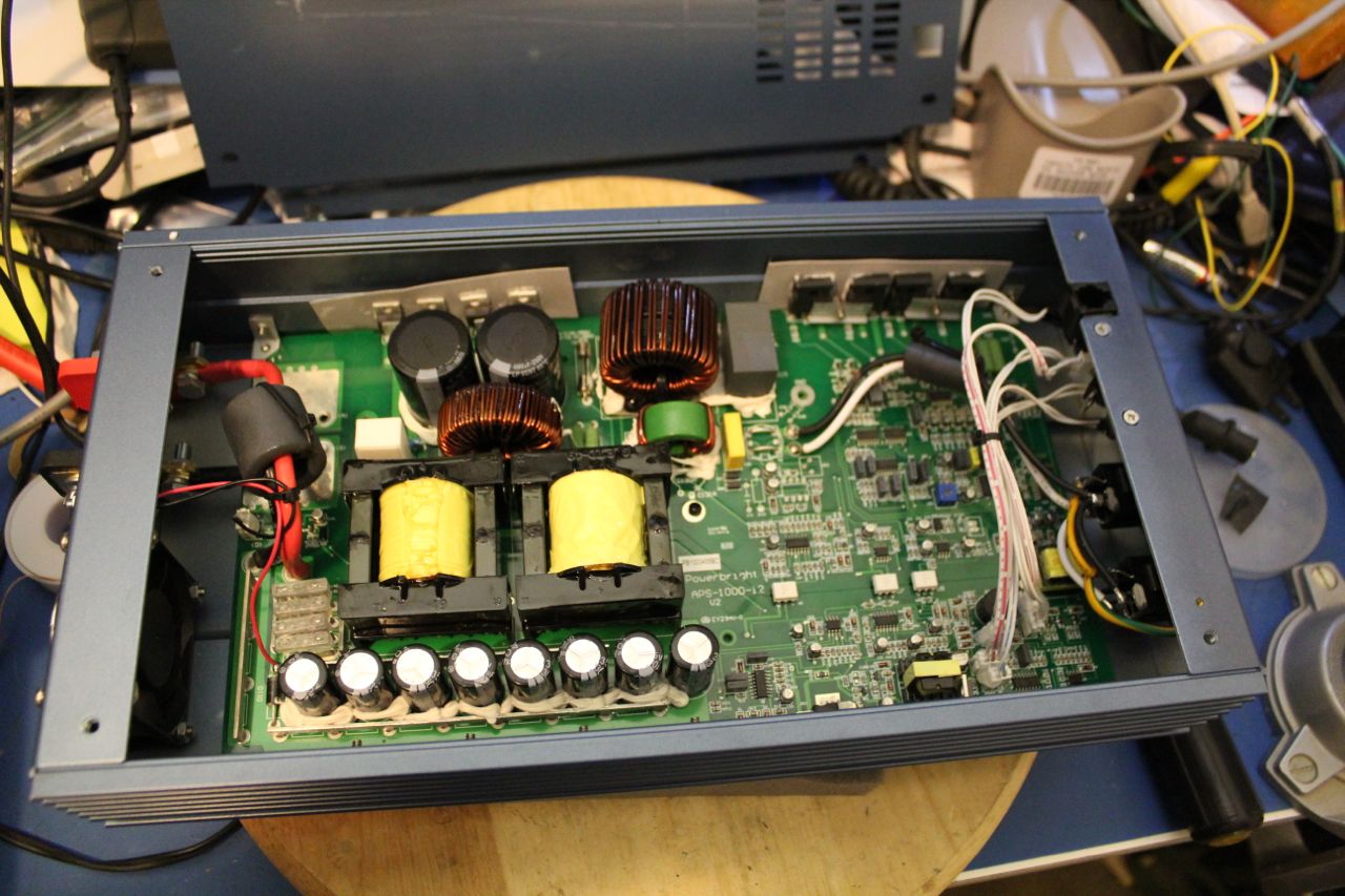
Bottom Cover Removed to Show Innards
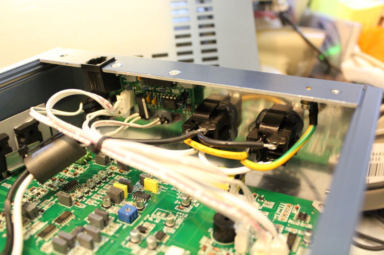
Inside of Front Panel
Visual inspection revealed no microcontroller or other highly integrated circuits. Everything appears to be discrete components, common 4000-series CMOS, and common linear ICs. There is one crystal, attached to a CMOS oscillator plus divider IC. There is one trimpot, which turns out to be an output voltage adjustment.
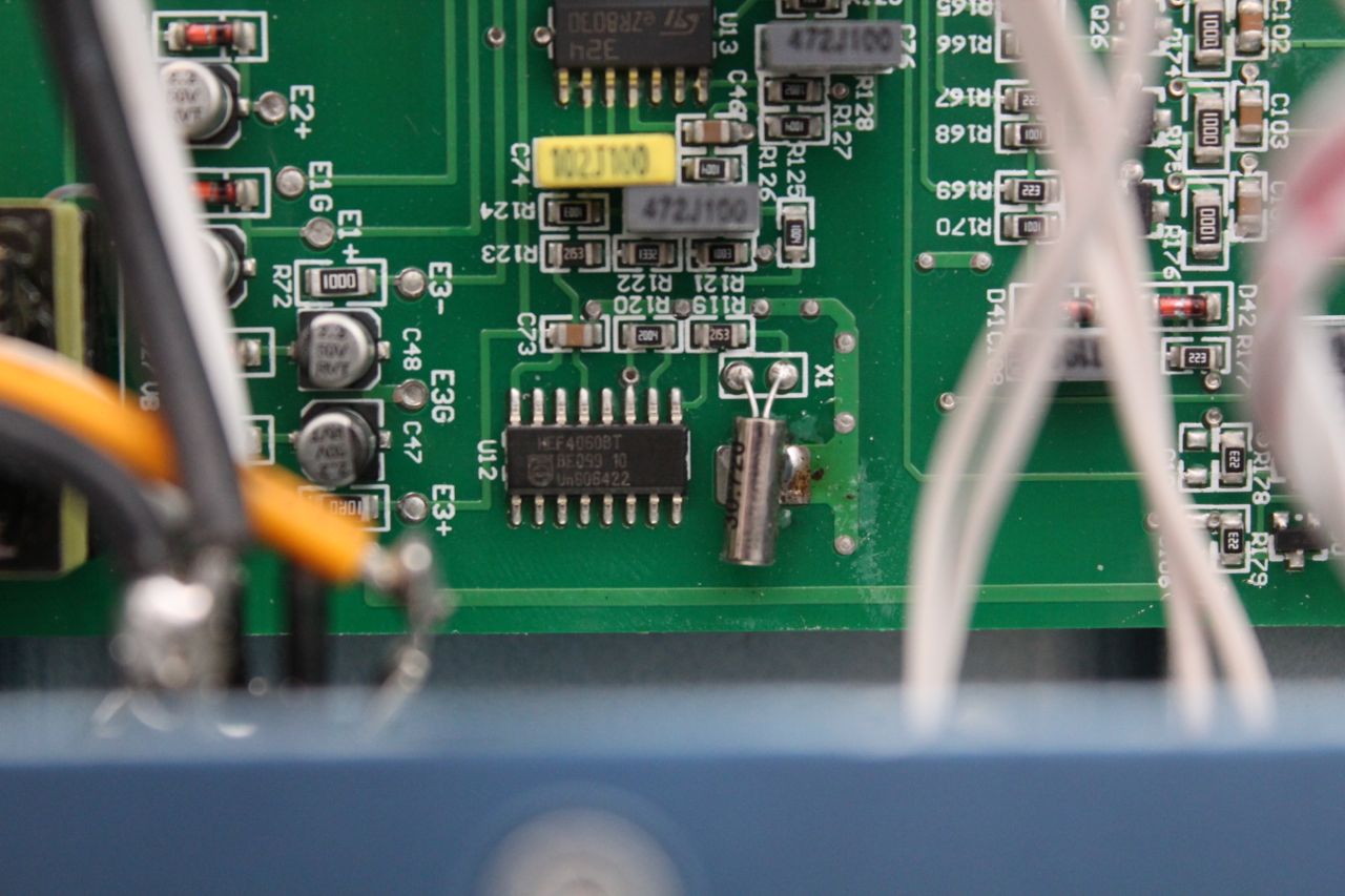
Crystal Oscillator and Divider Circuit
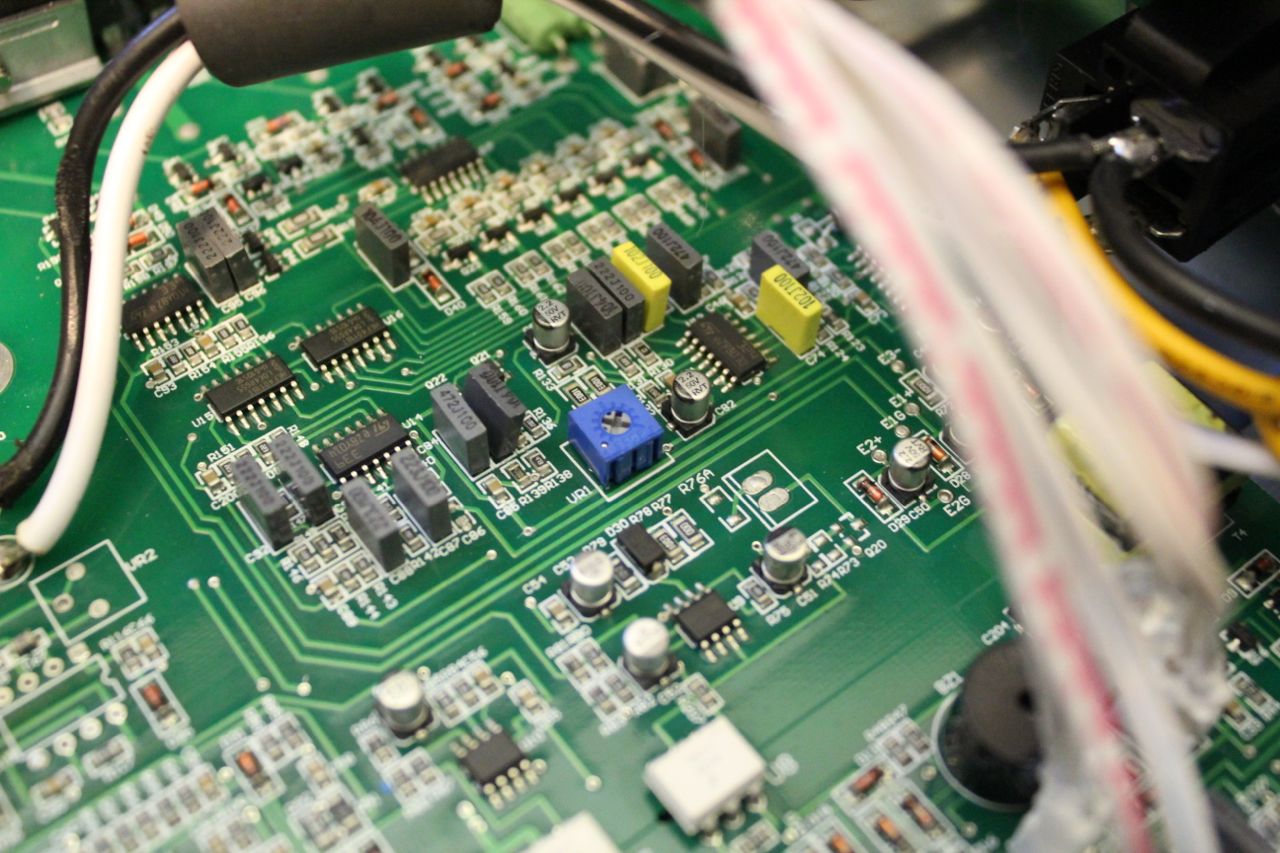
Output Voltage Adjustment Trimpot
The inverter does not bond neutral to ground, so I added a wire on the back of the output sockets for that (though I’ll eventually remove those sockets, and the neutral may or may not be bonded to ground when I’m done). Probing around shows a clean sinusoidal output, and the pulse-width modulated switching signal which is low-pass filtered to produce the clean AC output.
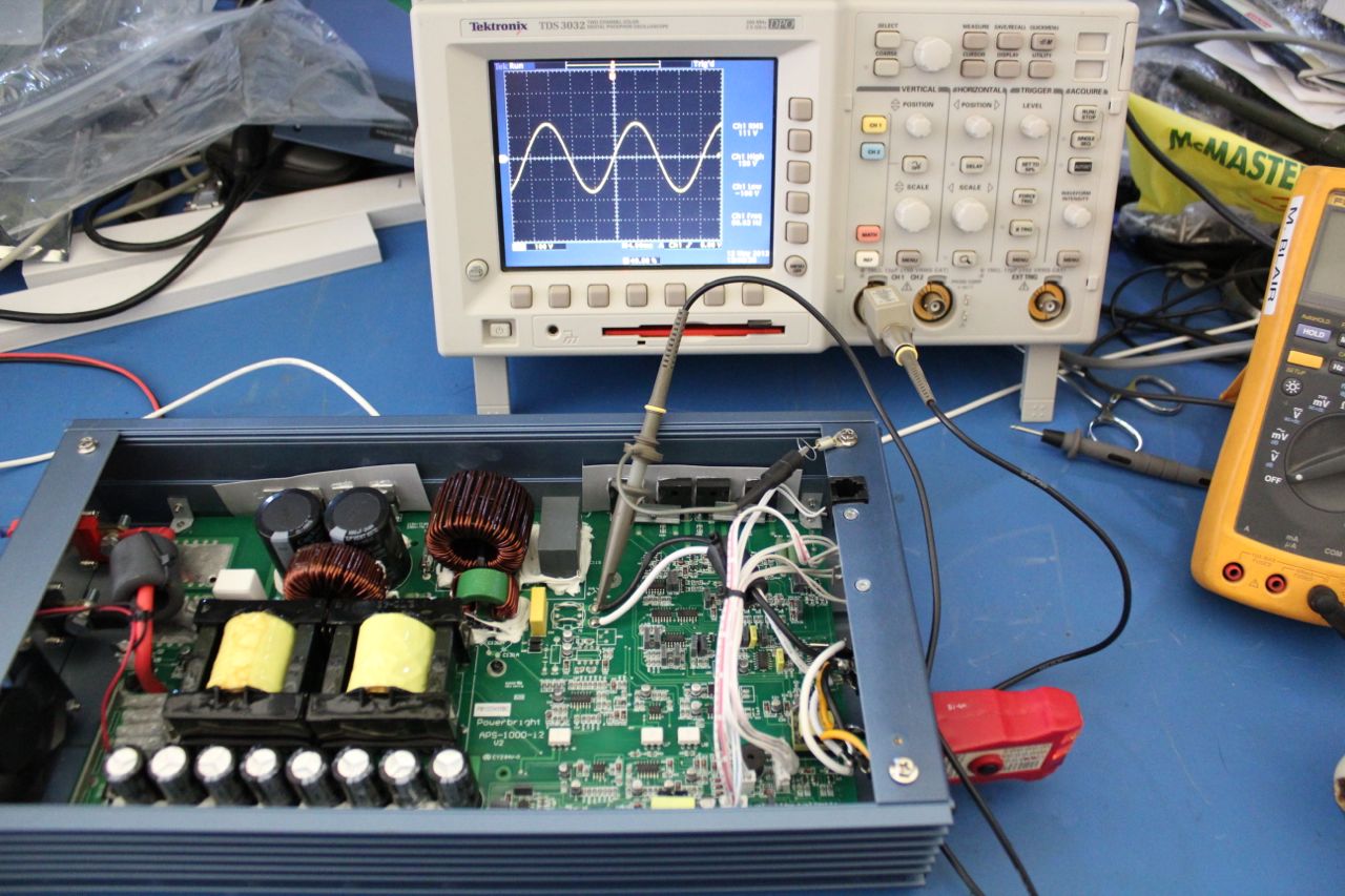
Poking Around Inside
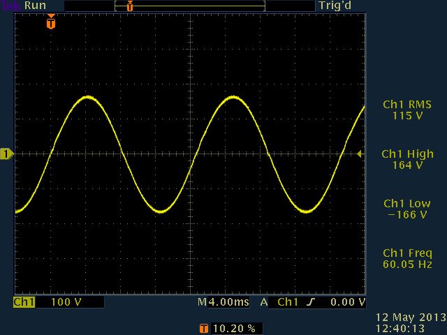
Clean 60Hz AC Output from Inverter
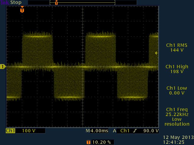
PWM Waveform Before Filtering
Close-up of PWM Waveform
My next tasks include:
- Figuring out how the 60 Hz sine wave reference is generated.
- Figuring out how to modify that reference to make an 800 Hz sine wave (actually, anything between 600 Hz and 800 Hz should satisfy the GP-7 according to its dataplate).
- Determining whether the output filter will work well at 800 Hz without modification. If its corner frequency is too low, then it might heat up too much once I increase the output frequency.
Hmmm,
The Crystal should be the reference, and there should be a Capacitor / Resistor on the inverter chip that regulates the frequency.
On my Circuit see, http://www.electrokits.com/downloads/pdf/TL494-datasheet-TI.pdf and look at Pins 5 and 6 on the circuit sample, they set the Frequency.
If you lookup the number on the inverter chip, they should have similar components and you can work out the duty cycle from the calc.
Regards
Ray Poularas
I haven’t found anything as advanced as a TL494 PWM regulator on the board yet. I think this one may be a discrete implementation. The crystal is connected to a 4060 oscillator + prescaler, and the voltage adjustment pot is in the vicinity of an LM324 quad op-amp. I found full line voltage in the general vicinity of the op-amp, so my starting guess before I start tracing out that circuit is that the line voltage is divided down and then compared to a reference sine wave to generate an error signal for the PWM control circuitry.
Oscillator chip:
http://www.nxp.com/documents/data_sheet/HEF4060B_CNV.pdf
There appears to be enough ICs in there to be a discrete PWM controller implementation, and my initial visual scan didn’t turn up anything more advanced than 4000 series CMOS and generic linear ICs.
I don’t know yet whether the crystal + divider circuit is the frequency reference for the PWM rate, the 60 Hz output, or both. I’m going to trace out that circuit before I probe it more, because I’ve already caused the supply to emit Unpleasant Noises when I touched some nodes in that general area with my scope probe.
Indeed,
If its making noises when you probe it you more than likely injecting noise into the circuit.
They can be susceptible to that, and RF may also upset it.
Knowing the designers of these things they are normally minimalistic in noise control and expect their calculations to be spot on. Having designed some electronics in my past I know that you always need to plan for the unexpected.
Sounds like your on the right track if there is no Switch mode controller chip than they may have duplicated the thing as you said in desecrate components.
Once you trace the circuit you will be in a better position to make a choice as to how to adjust the reference or oscillator.
RP
have a look at
http://f1frv.free.fr/main3p_490T-1.html
its a 400 Hz supply, but can be set easyly to 600 or 800 Hz
73s
dom