At the 22nd annual Military Radio Collectors Group meet in San Luis Obispo, CA, I gave a presentation on an interesting piece of equipment called Audio Frequency Monitor AN/PTA-1. This set allows wiretapping of both two-wire and ground-return field telephone lines, using several different intrusive and non-intrusive coupling methods.
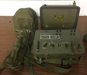
AN/PTA-1 on Display at 2017 MRCG Meet
I had never heard of this set before I bought mine a couple years or so ago. The technical manual that came with the set is dated from 1954, with changes made in 1960 and 1962. Since I haven’t seen the manual online before, I’ve scanned it:
I’ll also share my presentation slides from the MRCG meet:
Description
I’ll let the technical manual introduce this set:
Audio Frequency Monitor AN/PTA-1 (fig. 1) is a wire tapping device used to intercept communication signals transmitted over telephone lines and field cables where frequencies in the range of 200 cycles per second (cps) to 8,000 cps are used. The intercepted signal can be picked up in the headset assembly supplied with the equipment or recorded on a sound recorder. Recording equipment is not supplied as a part of Audio Frequency Monitor AN/PTA-1. The set is packed in two units for convenience of transportation and is easily transported by one man.
Audio Frequency Monitor AN/PTA-1.
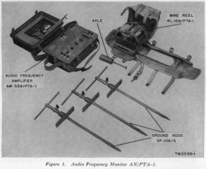
The major components of this set are Audio Frequency Amplifier AN-558/PTA-1, and a special canvas backpack.
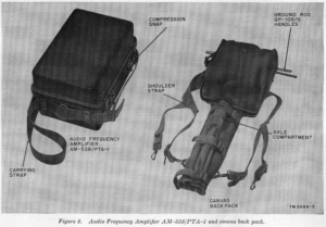
Audio Frequency Amplifier AM-558/PTA-1 and canvas back pack.
The amplifier has a weathertight cover and a carrying strap. The lid of the amplifier has storage space for a headset with extension cable, a clamp-on inductive pickup coil, and some insulation-piercing clips for making direct connections to insulated field phone wire.
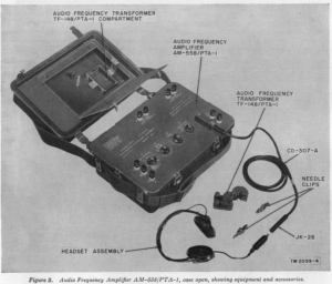
Audio Frequency Amplifier AM-558/PTA-1, case open, showing equipment and accessories.
The backpack carries three threaded ground rods, three threaded toe plates which allow the ground rods to be screwed into the ground without any noisy hammering, a spool of field phone wire, and an axle which allows the operator to quickly reel the wire in and out.
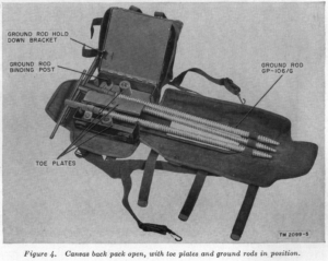
Canvas back pack open, with toe plates and ground rods in position.
The amplifier can be powered either by internal batteries (one each, BA-409/U and BA-415/U) or external power. In either case, it needs 6VDC 50mA for the tube filaments, and 90VDC 5mA for the tube plates. It has a minimum gain of 90dB at 1,000 cycles per second (cps), and a nominal frequency response of 200 cps to 8,000 cps. It has a switchable 300 cps high pass filter, and a switchable 3,000 cps low pass filter. It provides +10dBm of audio output power. Input impedance is adjustable from 20 ohms to 500k ohms, with an even higher impedance mode for direct connection to phone lines. It includes two lightning arrestors for the field phone connection, with two more spares stored inside the case. The set doesn’t include any built-in recording capability, but it can be used with external recording equipment such as Recording Equipment RC-169, Speech Recorder MC-502, or Speech Reproducers MC-503 and MC-503-A.
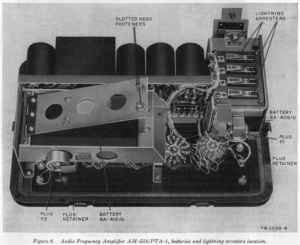
Audio Frequency Amplifier AM-558/PTA-1, batteries and lightning arrestors location.
The amplifier uses three tubes: two 1U4 pentodes, and one 3Q4 pentode. Volume control is via a switchable attenuator, rather than a potentiometer.
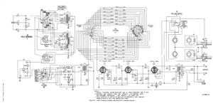
Audio Frequency Amplifier AM-558/PTA-1, schematic diagram.
Interception Methods
This set allows five different methods of interception. Before we get into them, it is important to understand that there are two distinct styles of wiring used with analog field phones. One style uses a pair of wires between stations. This style is preferable because it is less subject to crosstalk and other interference, and it offers fewer methods of surreptitious wiretapping of the circuit. But as an expedient, there is another style of wiring, in which there is a single wire between stations, with the circuit’s return path passing through the ground via ground stakes at each station. This second station has the advantage of using half as much wire, and it can also be employed to quickly return a damaged circuit to operation when one wire is broken.
The most straightforward interception method is to simply make a direct connection to the wires to be tapped. This method can be used with either two-wire or ground-return circuits. It gives the most reliable connection, but it is also the easiest method for the enemy to detect. The visible connection and/or wire insulation damage from a previous connection may be seen by the enemy. The enemy may also hear audible clicks when the connection is made, or measure a change in circuit characteristics due to loading from the amplifier and its wiring.
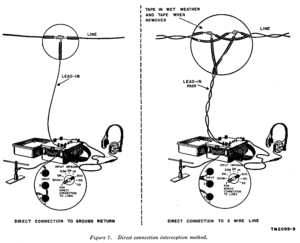
Direct connection interception method.
The next two interception methods involve indirectly coupling to the circuit either inductively or capacitively. These methods can be used for both two-wire and ground-return circuits. The set includes a clamp-on audio transformer which functions much like a clamp-on current probe. This transformer can be used to inductively couple to the circuit to be tapped. For capacitive coupling, no special equipment is needed; just wrap a piece of insulated wire around one conductor of the circuit to be tapped to couple to it capacitively.
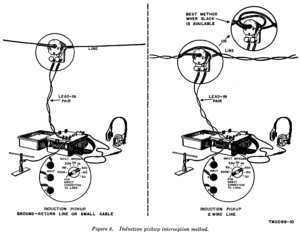
Induction pickup interception method.
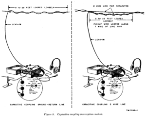
Capacitive coupling interception method.
The final two methods are especially interesting. They are only applicable for ground-return circuits. The operator can inductively couple to the circuit to be tapped with a large loop of wire laid on the ground. Or, the operator can electrically detect the ground-return current with two rods driven into the ground, far apart, along a line parallel to the circuit to be tapped. These two methods are more susceptible to crosstalk and interference than the other methods are, but they have the advantage of allowing a ground-return circuit to be tapped without direct access to the enemy’s wire. This might be the only way to tap an enemy’s well-guarded ground-return wire, since the enemy is likely to provide kinetic discouragement to anybody trying to tap their communication circuits. Even if the enemy didn’t intend to create a ground-return circuit, either an unintentional fault or intentional sabotage may cause a field phone circuit to pass some or all of its current through the ground, offering an opportunity to tap it from a safe distance.
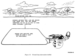
Ground loop interception method.
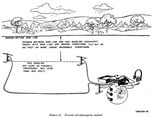
Ground rod interception method.
Epilogue
One of my MRCG buddies happens to be one of the very few people who might actually have a use for this interesting piece of kit: He’s a caver who makes ground-return field telephone systems for use in caving! I let him talk me out of owning this set. I’ve satisfied my curiosity about it, and now I get to enjoy having a QTH that is just a little bit less overstuffed with cool old junk.