Please note that I do not have any original manuals for this set, and I do not even have a complete set of copied manuals (for example, I do not have any aligment procedures, and I would have great difficulty understanding them even if I had them due to my very poor command of the German language). I cannot provide any further information beyond what is described here at this time, and I cannot provide manual photocopies or other printed information at this time. This page truly contains everything I know about the SEM-25!
Please comment me if you discover any errors in this paper.
I hope you find this information useful!
Description
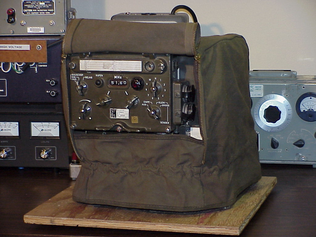
The SEM-25 is a West German short-range tactical vehicular VHF FM transceiver which was introduced in the 1960’s, and was apparently used until at least the 1980’s. Although surplus SEM-25 radios are not yet very common in the U.S., some have recently appeared on the U.S. surplus market from vendors such as Murphy’s Surplus Warehouse.
The SEM-25 covers 26.00 to 69.95 MHz, in 50 kHz steps. It is all solid-state, except for three tubes in the transmitter power amplifier. A SEM-25 system will typically consist of at least the following items:
- Transceiver chassis
- Control box (may be mounted on front of transceiver, or remotely)
- Mounting/power supply
- Power transient suppressor
- Antenna tuning unit
- Antenna
- Audio accessories ranging from a simple handset to several junction boxes and headsets
- Various cables
More complicated systems may consist of two SEM-25 transceivers and one EM-25 receiver, with lots of audio gear and cabling, thus providing a set with retransmission and intercom features.
So far, I have only obtained a transceiver chassis, control box and mounting, so I cannot provide much information about the antenna, antenna tuning unit, power surge protector or other accessories at this time. The audio connections on the control box and main chassis are compatible with common 1950’s U.S. audio accessories such as the H-33/PT handset and LS-166/U loudspeaker. Pictures I have seen of the correct German audio accessories (well, actually photocopied photocopied photocopies…) suggest that the correct German handset (called an H-33G) appears virtually identical to its U.S. counterpart, and the correct loudspeaker has a case like a U.S. LS-7 loudspeaker with a mounting like a U.S. LS-166. The headset looks a lot like a U.S. H-63/U with an AN/GSA-6 control box. The antenna whip elements are called MS118AK, MS117A and MS116A, and look very similar to U.S. elements with similar names, and the antenna base looks a lot like the U.S. MP-65. The knobs on the control box look just like 1950’s U.S. knobs. I’m really surprised at the similarities between this set and comparable U.S. sets, in spite of the fact that they were designed and built in different countries.
I first learned of the existence of the SEM-25 when I saw a pile of them on the shelves in the famous back room of Murphy’s shop in late 1998. Although I had never been very interested in foreign military gear before, the SEM-25 looked like a neat radio, so I talked my folks into getting me one for Christmas in 1998. My dad and I made the hour-long drive down to Murphy’s shop on Christmas Eve, and I picked out the nicest-looking radio from the pile. It was even gift-wrapped in a stylish olive drab canvas cover!
At the time, Mike was charging $350 for the SEM-25, and $250 for a smaller but similar-looking radio which he called a “SEM-20”. The smaller radio is actually an EM-25 receiver; it’s basically a receive-only version of the SEM-25. It’s easy to get confused about the features and identification of these two radios, because they both use the same control box and share many modules, so the EM-25 is prone to have stickers which say “SEM-25” (or even “SEM-35”; it shares two internal modules with the SEM-35 backpack transceiver) on and inside it, and it will have controls for transmitting functions which it does not perform.
The “SEM” in “SEM-25” is short for “Sender-Empfangsgerät”, which is German for “transmitter-receiver”. Similarly, the “EM” in “EM-25” is short for “Empfangsgerät”, which is German for “receiver”.
Specifications
General
| Modes | Simplex, retransmit |
|---|---|
| Frequency range | 26.00-69.95 MHz |
| Channel spacing | 50 kHz |
| Number of channels | 880 |
| Channel selection | 44 1-MHz bands, 20 50-kHz channels each |
| Programmable channels | 10 |
| Modulation | FM |
| Operation, including frequency selection | Operated from a transceiver-mounted control box, or from a relocatable control box in vehicle (max. cable length 10m) |
| Transmitter operation |
|
| Remote input and output arrangement | From telephone remote control over field phone wires, up to 3 km long, max. resistance 480 ohms |
| Temperature range | Operating range from -45°C to +60°C |
| Overvoltage protector | For transients up to 65V from the battery regulator |
| Power supply | 24V battery supply, negative ground, permissible voltage range 21V to 29V, short term overvoltage up to 32V |
Transmitter
| Output power | High: 15 W Low: approx. 1 W |
|---|---|
| Calling frequency | 1600 Hz |
| Audio input |
|
| Warm-up time | approx. 30 seconds |
Receiver
| Sensitivity | <= 0.5 µV for 20 dB s/n with 1000 Hz modulation and 10.5 kHz deviation |
|---|---|
| Bandwidth | >= 30 kHz at 6 dB points |
| Selectivity | +/- 50 kHz at 80 dB points |
| Audio output |
|
Power Supply
| Voltage | 24V battery (21V to 29V), negative ground, permissible short term overvoltage up to 32V |
|---|---|
| Power requirements, RX | approx. 10 W |
| Power requirements, TX Low | approx. 50 W while transmitting |
| Power requirements, TX High | approx. 80 W while transmitting |
| Power requirements, TX Low or TX High | approx. 29 W when not transmitting |
Sizes and Weights
| Item | Height (mm) | Width (mm) | Depth (mm) | Weight (kg) |
|---|---|---|---|---|
| Control box | 174 | 228 | 75.5 | 2.54 |
| Transceiver | 222 | 268 | 255 | 14.59 |
| Transceiver mount | 120 | 320 | 300 | 9.43 |
| Receiver | 222 | 196 | 255 | 11.08 |
| Receiver mount | 120 | 320 | 230 | 6.68 |
| Antenna tuning unit | 122 | 290 | 110 | 3.70 |
| Overvoltage protector | 93 | 250 | 126 | 2.62 |
| Spares case | 48 | 140 | 140 | 0.73 |
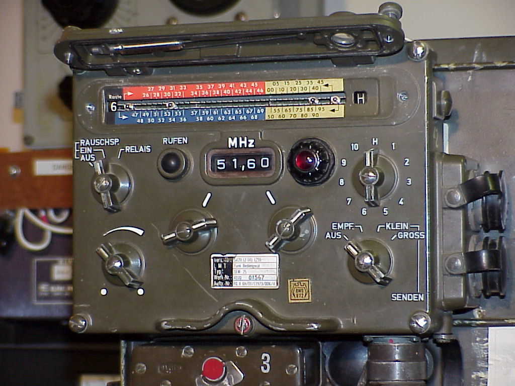
Controls
This section decribes the functions of the controls on the SEM-25 control box.
| Ref. | Description |
|---|---|
| A | Channel programming drum (behind cover) |
| B | Call button: Keys transmitter, sends 1600 Hz tone |
| C | Squelch |
| D | Volume |
| E | Manual tuning, 1 MHz steps |
| F | Manual tuning, 50 kHz steps |
| G | Power |
| H | Channel selector (H = manual tuning) |
| I | Power-on light (turn bezel to dim) |
Power Switch Settings (Ref. G)
| AUS: | Off |
|---|---|
| EMPF: | Receive-only |
| SENDEN KLEIN: | Transmit/receive (low power) |
| SENDEN GROSS: | Transmit/receive (high power) |
Squelch Switch Settings (Ref. C)
Note: Squelch is opened by carrier level, equivalent to “old” mode in U.S. radios.
| RAUSCHSP. AUS: | Squelch off |
|---|---|
| RAUSCHSP. EIN: | Squelch on |
| RELAIS: | Relay (retransmit) |
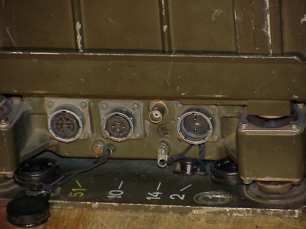
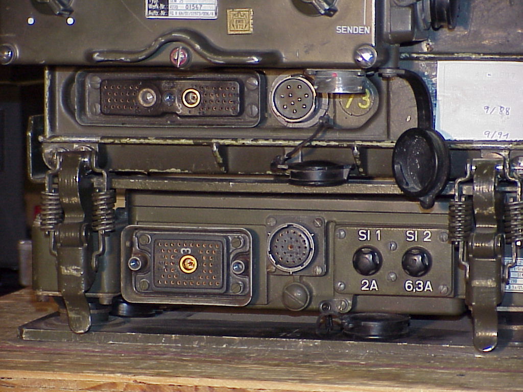
Connectors
This section describes the functions of the external connectors on the SEM-25.
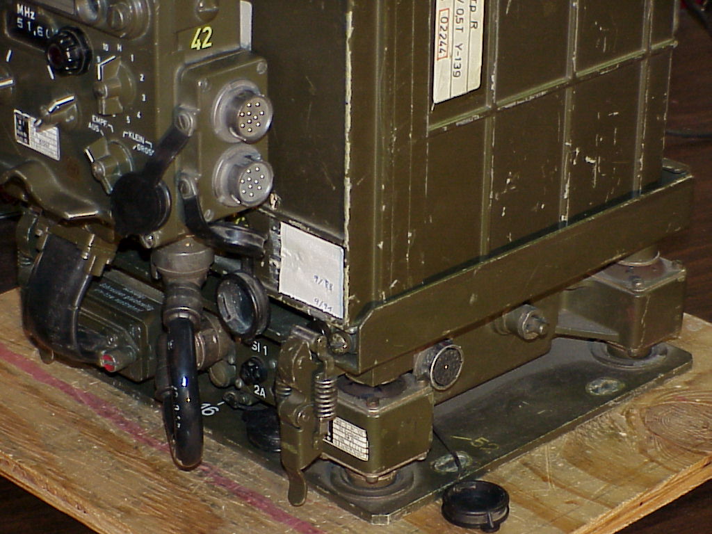
| Ref. | Description |
|---|---|
| J | From transceiver #1 in multi-radio sets |
| K | Antenna tuner control |
| L | Antenna RF |
| M | Power input |
| N | Mounting/transceiver interconnect |
| O | Audio |
| P | Control box/mounting interconnect |
| Q | Receiver fuse (2A) |
| R | Transmitter fuse (6.3A) |
| S | To transceiver #2 or aux. receiver in multi-radio sets |
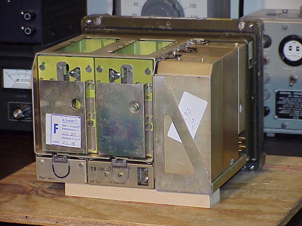
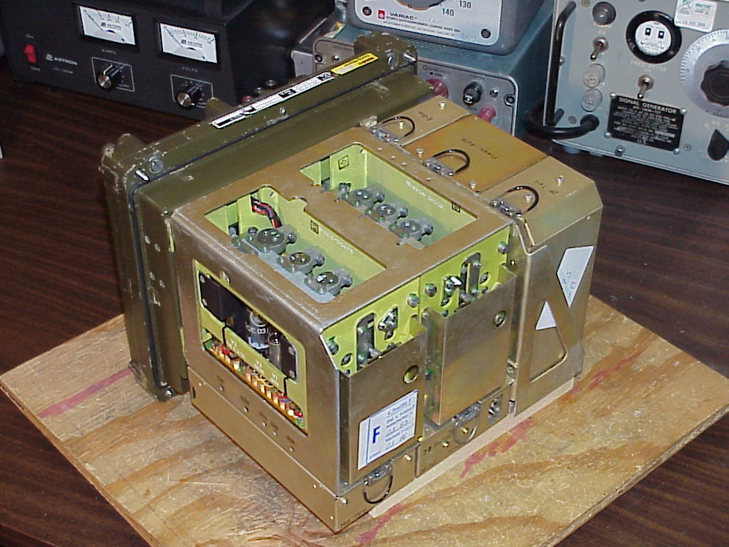
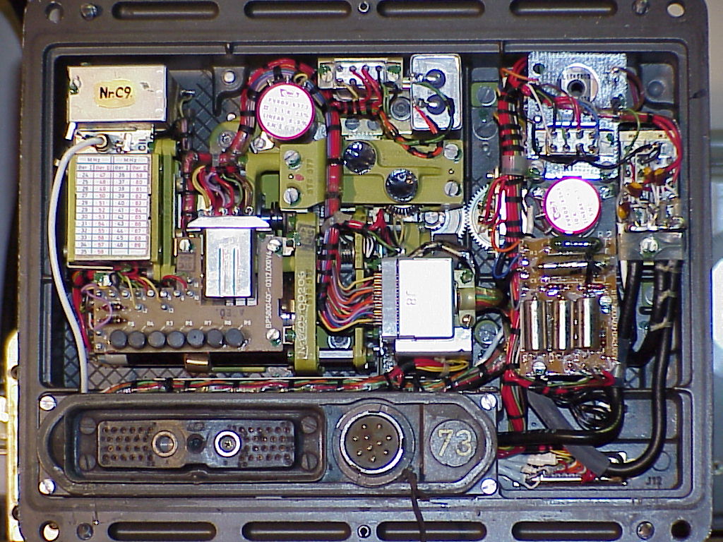
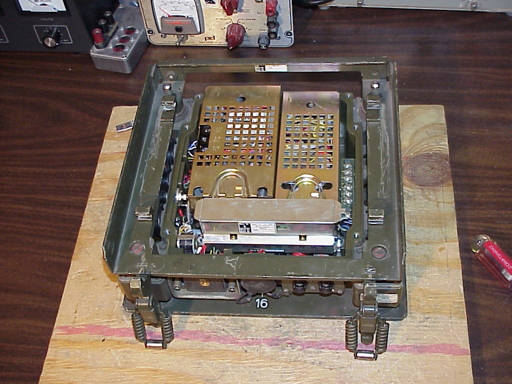
Modules
This section identifies the SEM-25’s major internal modules. Note that two of the modules (as noted below) are also used in the SEM-35 backpack/vehicular transceiver.
| Ref. | Description |
|---|---|
| N | Mounting/transceiver interconnect (external) |
| O | Audio connector (external) |
| P | Control box/mounting interconnect (external) |
| Q | Receiver fuse (2A) (external) |
| R | Transmitter fuse (6.3A) (external) |
| T | Transmitter RF |
| U | Receiver RF |
| V | Modulator amplifier, 1600 Hz tone generator, and 11.5 MHz discriminator for automatic frequency control (AFC) of transmitter |
| W | Audio amplifier |
| X | Receiver power supply and control amplifier |
| Y | Frequency synthesizer (also used in SEM-35) |
| Z | IF (Intermediate Frequency) module (also used in SEM-35) |
| AA | Plugs for test box |
| BB | 10-frequency crystal oscillator |
| CC | Receiver servo |
| DD | Transmitter servo |
| EE | Transmitter power supply |
| FF | Motor drive power supply for external antenna tuner |
| GG | Relays for interconnect of multiple transceivers |
| HH | 600 ohm balanced audio connections |
Internal Adjustments
While we have the case open, here are some of the major internal adjustments:
| Control | Label | Location | Function |
|---|---|---|---|
| R36 | Rauschperre | Audio amp. (Ref. W) | Squelch level |
| R5 | NF-Pegel | Audio amp. (Ref. W) | Audio level |
| R13 | Eing. | Mod. amp. (Ref. V) | Mod. amp. input gain |
| R26 | Ausg. | Mod. amp. (Ref. V) | Mod. amp. output gain |
| R38 | Tacho | Rx power supply (Ref. X) | Stepping speed trim (?) |
Schematics
The diagrams in this section were scanned at 150 pixels per inch, and you will probably need to use an external graphics-editing program to print them (simply clicking your browser’s “Print” button probably won’t work well).
The diagrams were all scanned from photocopied manuals, and the originals are just as blurry as the scans, so don’t bother asking for photocopies of the schematics! :-)
Block Diagrams
| Description | File | Size |
|---|---|---|
| Transceiver | blk01.gif | 1100×1338, 33k |
| Frequency selection | blk02.gif | 1100×1540, 44k |
| Receiver | blk03.gif | 1172×946, 20k |
| Transmitter | blk04.gif | 1082×888, 12k |
| Antenna tuner (external) | blk05.gif | 948×1240, 15k |
Schematic Diagrams
The “Ref.” column shows the corresponding reference letters from the module identification pictures (where applicable), to help you figure out which part of the radio is described by each schematic.
| Description | Ref. | File | Size |
|---|---|---|---|
| Wiring (main chassis) | — | sch01.gif | 1744×1232, 90k |
| Transmitter RF | T | sch02.gif | 1744×1232, 70k |
| Receiver RF | U | sch03.gif | 1744×1232, 70k |
| Modulator amplifier module | V | sch04.gif | 1744×1232, 62k |
| Audio amplifier module | W | sch05.gif | 1744×1232, 55k |
| Receiver power supply module | X | sch06.gif | 1744×1232, 66k |
| Frequency synthesizer module | Y | sch07.gif | 2381×1231, 117k |
| IF module | Z | sch08.gif | 2539×1232, 84k |
| 10-freq. crystal oscillator | BB | sch09.gif | 1193×768, 17k |
| Receiver servo | CC | sch10.gif | 1196×778, 38k |
| Transmitter servo | DD | sch11.gif | 1172×809, 19k |
| Control box | — | sch12.gif | 3042×1226, 104k |
| Wiring (mounting) | — | sch13.gif | 1744×1232, 94k |
| Transmitter power supply | EE | sch14.gif | 778×1159, 36k |
| Motor drive power supply | FF | sch15.gif | 1187×772, 26k |
| Interconnect relays | GG | sch16.gif | 1197×794, 36k |
| Transient protector (external) | — | sch17.gif | 1201×790, 34k |
| Antenna tuner (external) | — | sch18.gif | 1744×1232, 68k |
English/German Translations
This section lists rough translations of some German words, phrases and abbreviations as used in the SEM-25’s schematics, module labels, etc. My command of German is very poor, so there may be mistakes here… please comment if you can correct any of my translations!
- Abstimmgerät
- Radio tuner (tune + apparatus)
- Abstimmteil
- Radio tuner section (tune + part)
- Additionsstufe
- Addition stage
- Anschluß
- Connection
- Antennen
- Antennas
- Antrieb
- Drive, driver, motor
- Ausgang
- Output
- Bausteinträger
- Component carrier
- Bauteile
- Components
- Bedien
- Control head
- Begrenzer
- Limiter
- Blockschaltbild
- Block diagram
- Bordbatterie
- On-board battery
- Bordverstärker
- Intercom (on-board + amplifier)
- Diskriminator
- Discriminator
- Eingang
- Input
- Einsatz
- Part, component
- Empf.
- Receive or receiver
- Empfänger
- Receiver
- Endstufe
- Output stage
- erdfrei
- Balanced (i.e. “balanced line”; literally, “ground-free”)
- Frequenzaufbereitung
- Frequency synthesizer
- Funk
- Radio
- geschlossen
- Closed
- gezeichnet
- Drawn
- gross
- Large
- Grundplatte
- Mounting (base + plate)
- HF
- Radio frequency (RF)
- Hinweis
- Note
- im
- In
- Kanalwahl
- Channel selection
- klein
- Small
- Leitung
- Line, wire
- Ltg.
- Line, wire
- Masse
- Common, ground
- Mischstufe
- Mixer
- Netzgerät
- Mains power adapter
- NF
- Audio frequency
- Oberton
- Overtone
- offen
- Open
- Oszillator
- Oscillator
- Prüfgerät
- Test meter
- quarz
- Quartz
- rauschperre
- Squelch (noise + stop)
- relais
- Relay, retransmit
- rufen
- Call
- ruhezustand
- Off-state
- senden
- Transmit
- Sender
- Transmitter
- Servoverstärker
- Servo amplifier
- Steuerverstärker
- Servo amplifier
- Stromversorgung
- Power supply
- Teil
- Part
- Transientschutz
- Transient protector
- Treibertufe
- Driver stage
- Trennstufe
- Divider stage
- Umwandler
- Converter
- Verstärker
- Amplifier
- Vorstufe
- Input stage
- ZF
- Intermediate frequency (IF)
Credits
This work would not have been possible without the generous assistance of the following people:
Pictures were taken with a Sony MVC-FD91 digital camera. Reference letters were added with Visio 4 on a Windows NT box; all other image editing was performed with xv and gimp on a Redhat Linux system.
Scanned documents were scanned with a Umax Astra 1220S scanner and the SANE software under Redhat Linux, and then edited with xv and gimp.
Hello Bruno !
You can find the schematic diagram of the control-Box in the upper Part of this page (Schematic Diagrams –> Sch12.gif) – and also the schematic of the audio acessory as the Handset H-33. I think the problem is that you don’t have any power for your ANR-circuit supplied via the U-77-Connector.
73,
Klaus, DL4FCY
Hello
I would like to ask for some information regarding the values of the following components from antenna tuner schematic sch18.gif
I have two antennae and want to use them for CB27 without the big antenna tuner. I just want to add similar LC external components and tune the antenna to 27mhz.
I have miniVNA and may fine tune it. I just need rough estimation for:
L3
C22
C24 – 82pF
L1
L2
Thank you
Hi Pavlik !
If you want to use your antennas for 27 MHz only, then, for my opinion, it would make sense to buy a cheap little matchbox for CB-devices, because the bandwith of the antenna is probably to small for working on different channels, if you want to do so. If you only want to work always on the same channel, you can align the antenna for the best swr, and then you don’t need a matchbox.
The original antenna tuner (AGAT) was developed, so that it was possible to use one antenna für the complete frequency range (26 – 70 MHz). I use my SEM 25 with a manual Yaesu FC-700-Tuner, so I can transmit with my antenna (modified CB-Mobile-Antenna INDOOR) on 10m FM. The AGAT is connected to the SEM 25- Mounting, so I can see if the switched (Control-Box) and indicated frequency on the top of the AGAT are the same.
Please refer the CB-regulations in your country, because in Germany the last Number of the frequencies for CB always is “5”, for example, Channel 4 is 27,005 MHz. Unfortunately the SEM 25 only switches in 50 kHz-Steps, so that there is a difference of 5 kHz between the selected frequency of the SEM 25 and the correct CB-frequency…
73,
Klaus, DL4FCY
Hello Klaus
Thank you for the fast reply. I am intending to use the antennas with standard CB radio, set properly to the country channel list.
Thanks to the warm weather, I spend some time with the NanoVNA and the antenna.
from yesterday:
3 element – https://drive.google.com/open?id=1mLbAtVff_F-SBY951dkwNm-GBGxr6oca
2 element – https://drive.google.com/open?id=1thoth4Q_eyqYJd7PdXiC9DyGmWBQ8fbx
3 element PC soft after calibration – https://drive.google.com/open?id=1GoQ7CzmAhY6w-fRzZYyHveISXzG_VN45
3 element tuned with L to GND and C in parallel. – https://drive.google.com/open?id=1wCJQqwdlCZ0AZo2pT6kZaVKmmuEEktxp
seems possible to make simple transmatch for CB, just need to dig for some old trimmer caps
Will post results when the antenna is installed.
Hello @ all !
Here is a information for all who are searching for mil-rig and accessories: One of the “better sources” for olive-green mil radio-stuff in germany is closed ! http://www.helmut-singer.de in Aachen unfortunately doesn’t exist anymore. For many years it has been a competent supporter for mil-collectors around the globe – not only for hardware – they nearly always had a answer questions round about mil-radio and much more.
73,
Klaus, DL4FCY
Hello SEM-25 community !
After a long time today I can proudly announce that my SEM 25 is working again !!! After getting the complete technical documentation I tried – again – to get the radio back to life-together with the SEP 25. After doing the re-adjust of the voltage-delivery for receiver and transmitter, and after the re-alignment of the tubes the radio began to do what it was made for (many years ago…in 1969-I found the stamp inside the chassis). Unfortunately I changed V1 to the well-known QQE-03/12, and it didn’t worked well. Later I replaced it with the original tube QQE-03/12Y-and that’s been a part of the problem. Then I changed the modulation amplifier, and now its back to life !!!!
Many times ago I’ve sent the Technical documentation (TDv 5820-046/40) to Mark. Maybe it’s possible to host it here on the page ?
73,
Klaus, DL4FCY