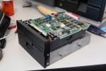
This Kaypro II computer has led a hard life, but it’s on the road to recovery now. A previous owner has modified it quite a bit, but some of the modifications are hack-jobs. I’ll probably need some help identifying some of the upgrades to determine whether I want to keep them or back them out, but there are a few changes that are definitely coming out.
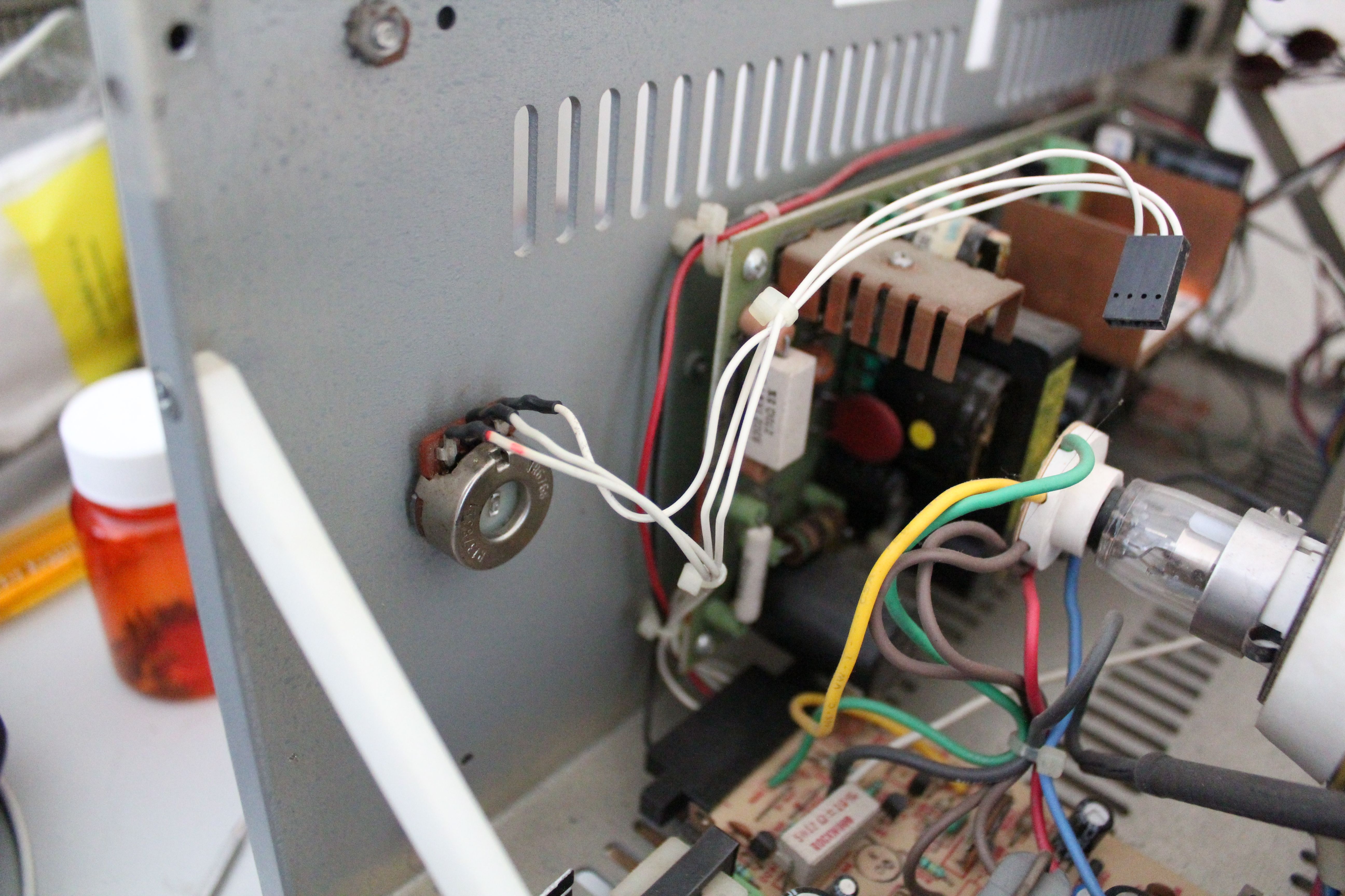
The worst offense was the relocation of a contrast control (it’s labeled “BRIGHTNESS”, but it’s technically a contrast adjustment) from the back panel to the front. The control is simply a potentiometer inline with the video signal wires from the main board to the monitor board. It acts as a resistive voltage divider in the luminance signal, while the sync signals are left alone. The normal connection between these boards is just a few unshielded wires; video bandwidths were low in those days, and shielding was a bit of an afterthought.
The original connection was pretty short, and the wires weren’t nearly long enough to reach to the new location on the front panel. So, the previous owner extended the wires… with speaker cord. And spliced the speaker cord to the original wires with wire nuts. Yes, you read that correctly: WIRE NUTS. Big orange ones.
The front panel has a few holes for me to patch up. One for the contrast control, one for the reset button (also relocated from the rear panel), and one for a toggle switch connected to an upgrade board that’s plugged into the CPU socket. There are also signs of some previous modification inside that has been removed: a new cable was spliced into the power harness, and an RCA jack was mounted on the rear panel, both with their connections left dangling inside the case. I have no way of knowing what they might have been connected to, but there are some foam tape remnants on top of the floppy drive subchassis that might have held some sort of board in place.
It’ll take a while for me to reverse-engineer the various modifications to determine what should stay, what should stay be be re-implemented, and what should go. The system probably needs repairs too, and I’m not quite ready to try applying power to it yet. But I’ve already undone that terrible contrast control hack, just so I can sleep at night.
-
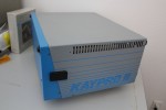
- Side view, with that lovely Kaypro II logo.

-
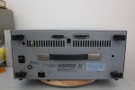
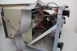
- Rear panel.

-
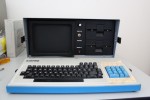
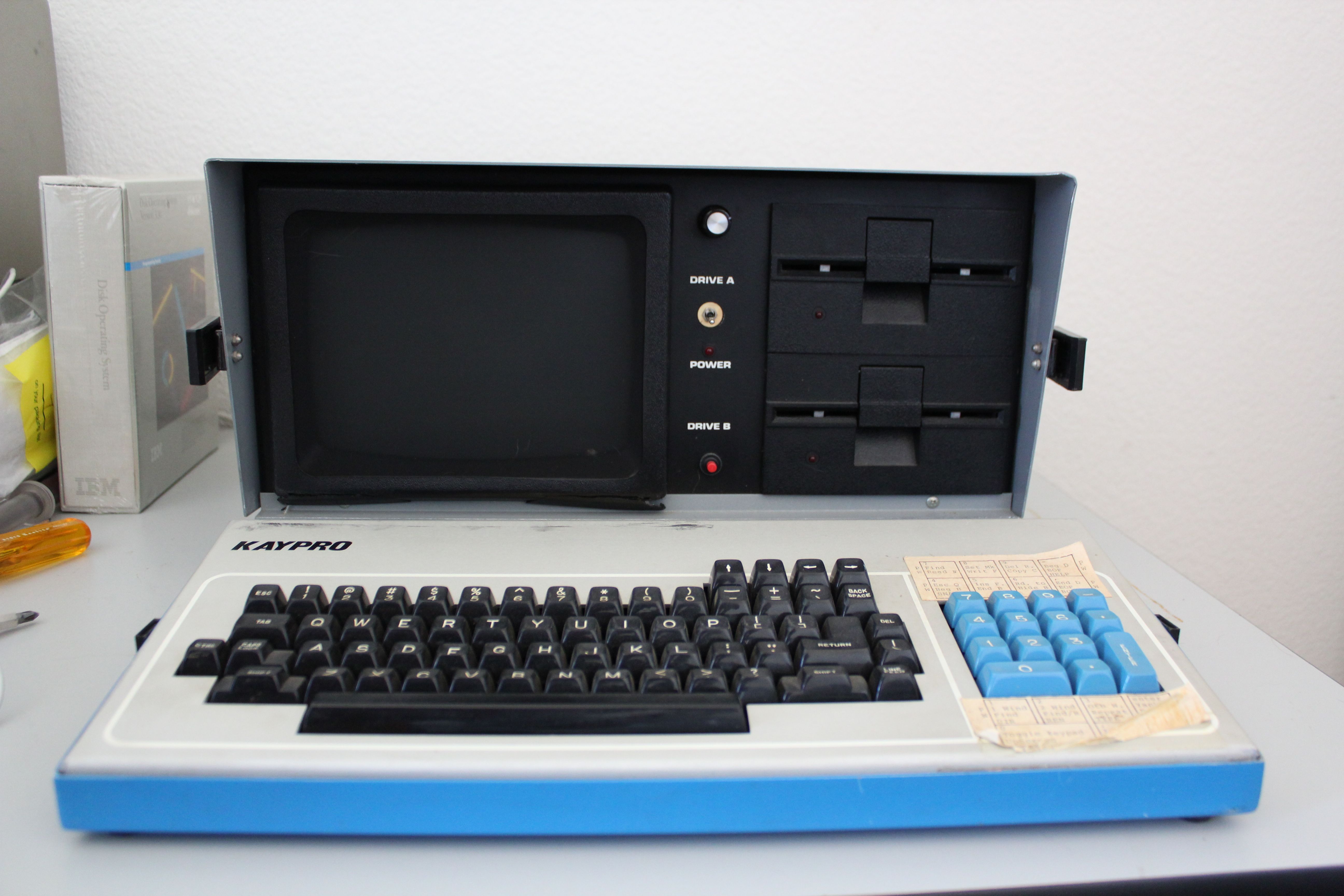
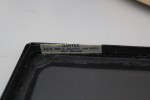
- Front view.
-
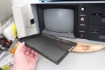
- Add-on fabric anti-glare screen. I may or may not keep it, since it has gotten pretty grungy.
-
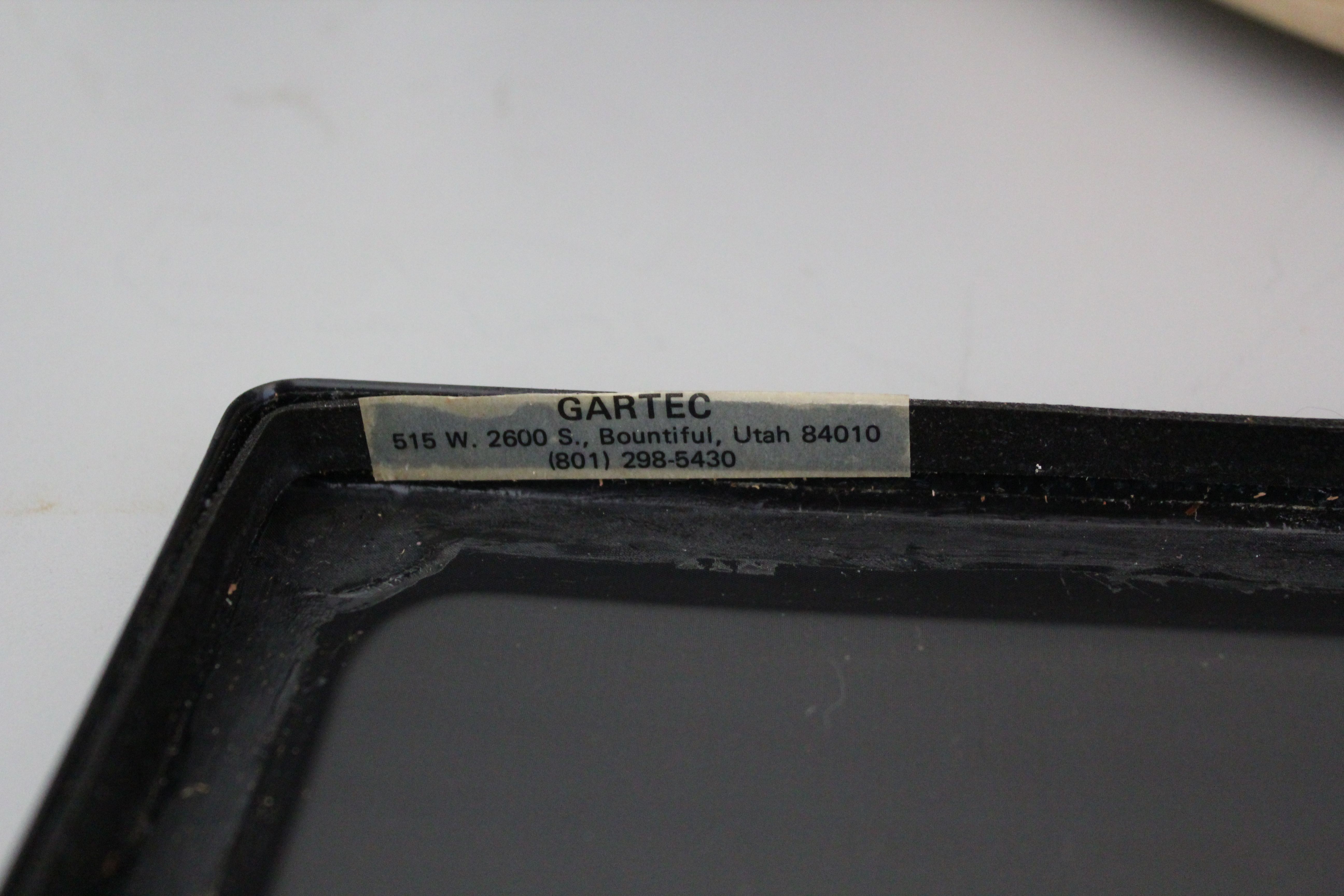
- Anti-glare screen was made by Gartec.
-
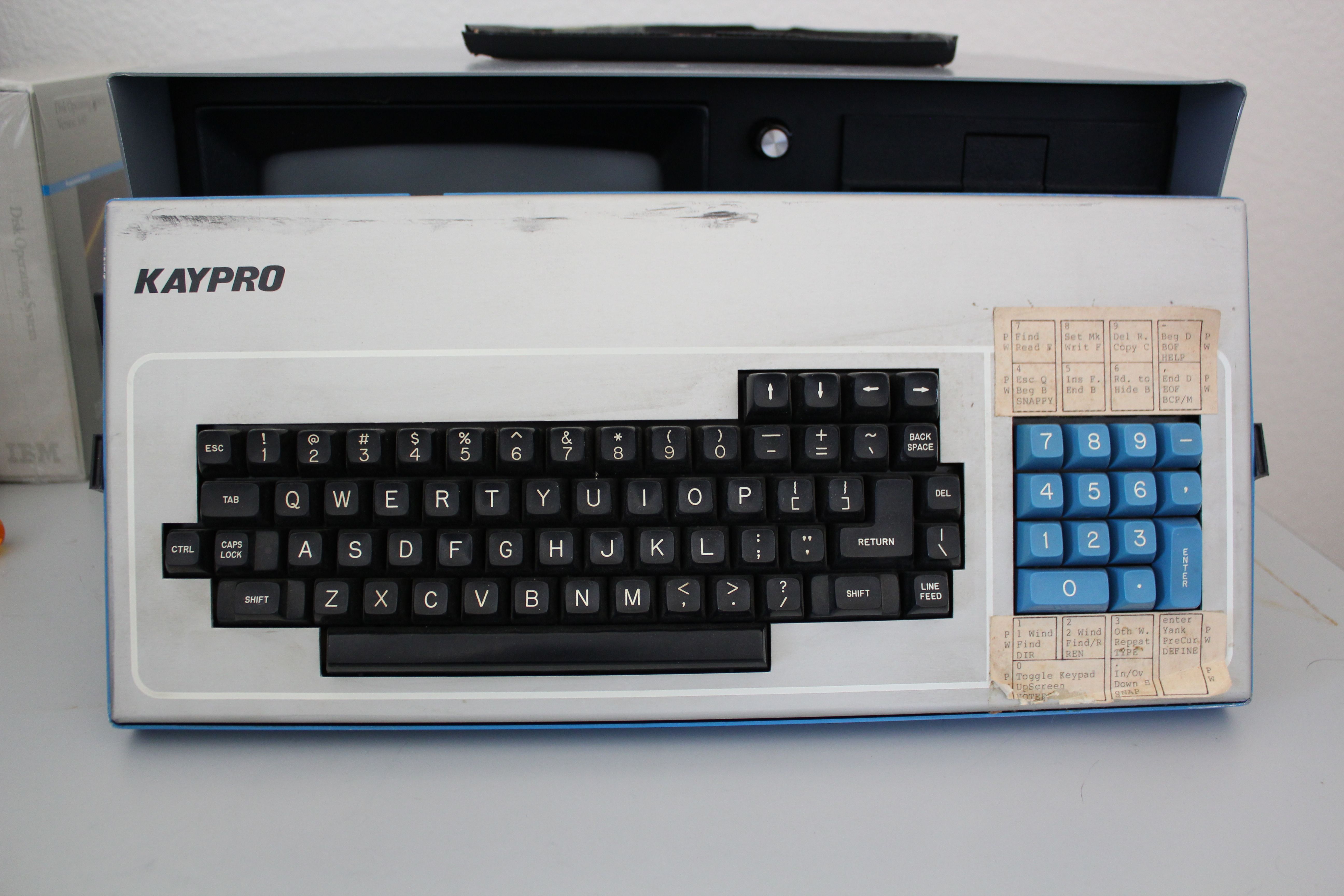
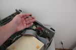
- The keyboard.
-
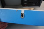
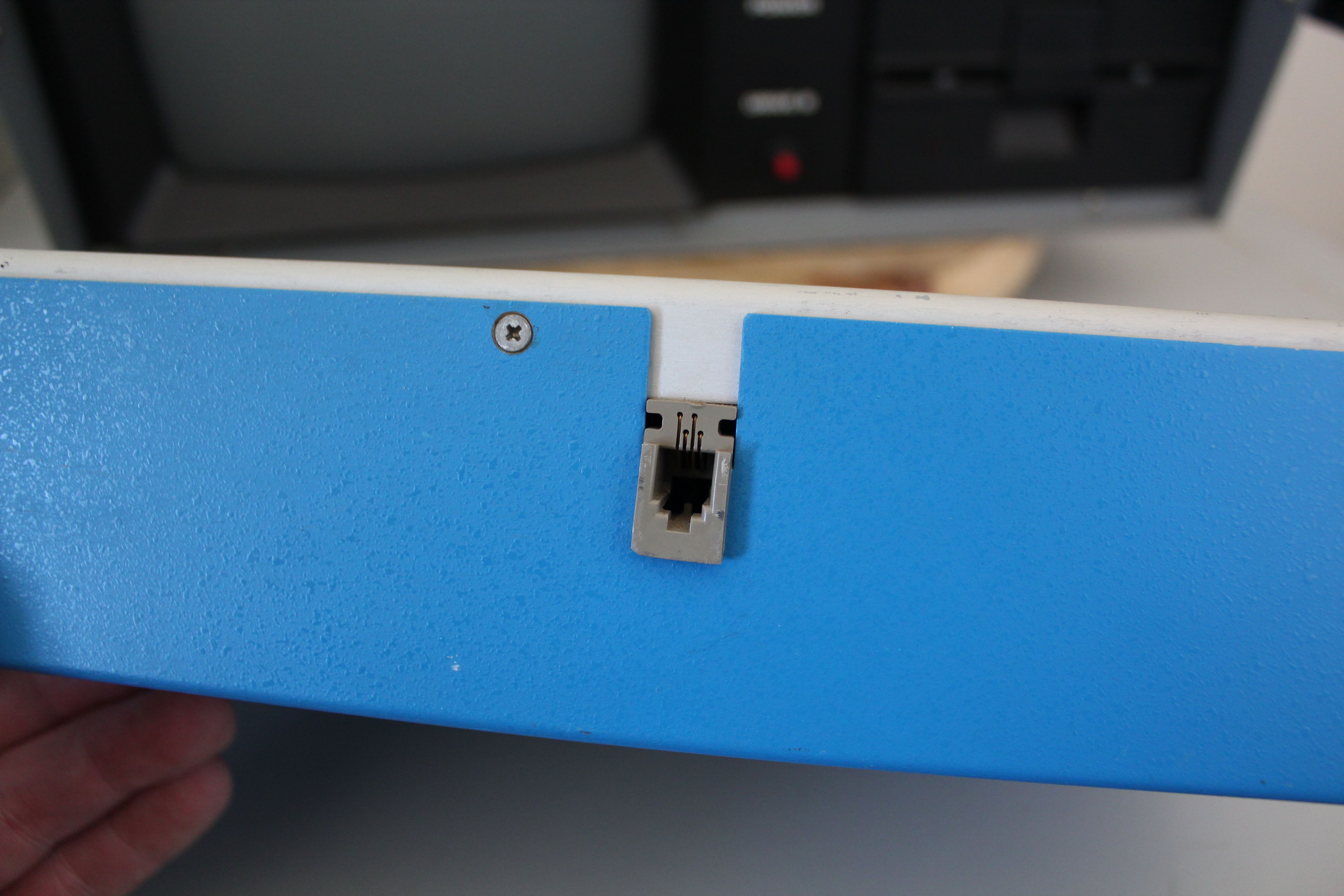
- Keyboard connections are 4-pin modular handset jacks.
-
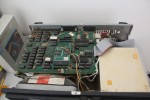
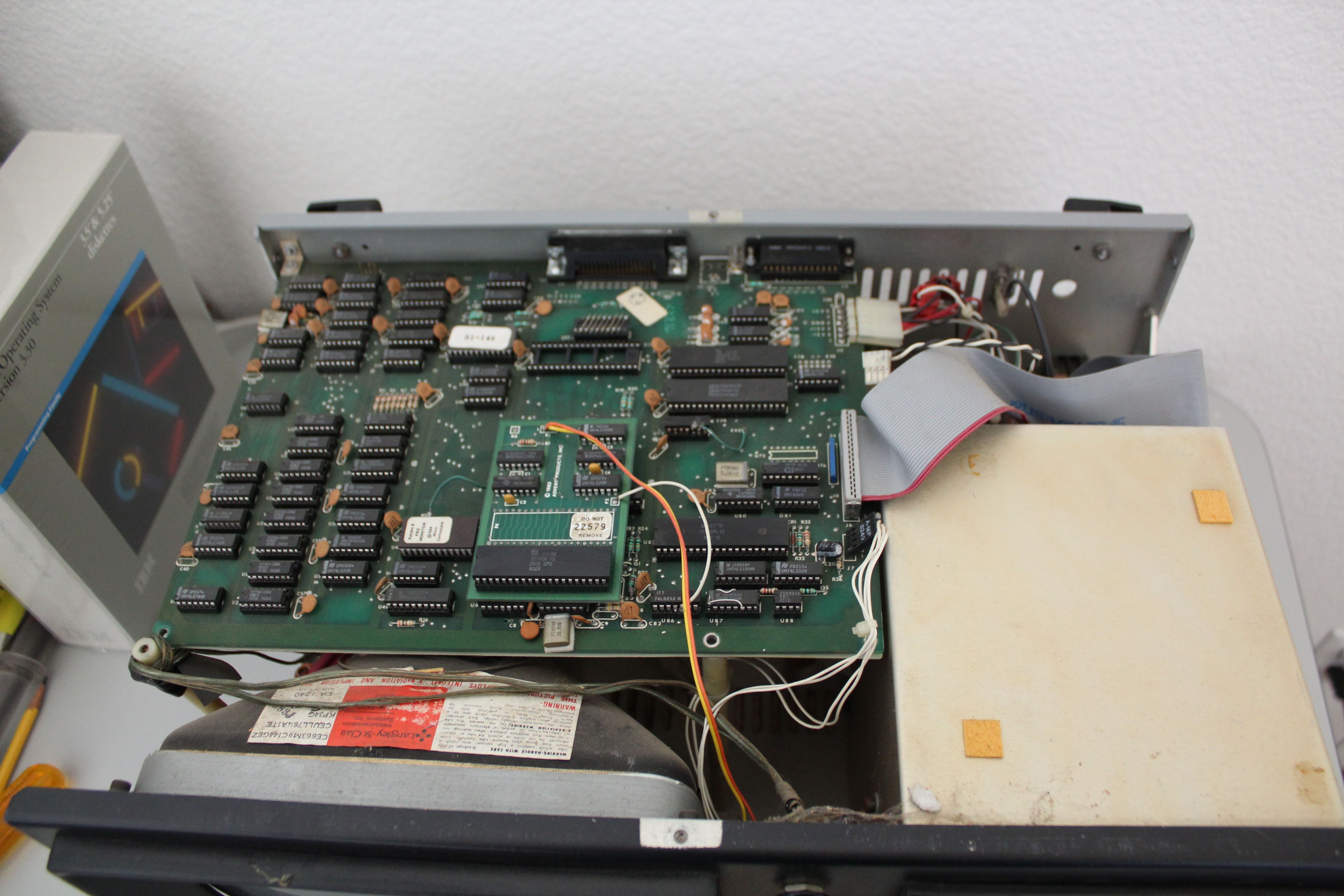
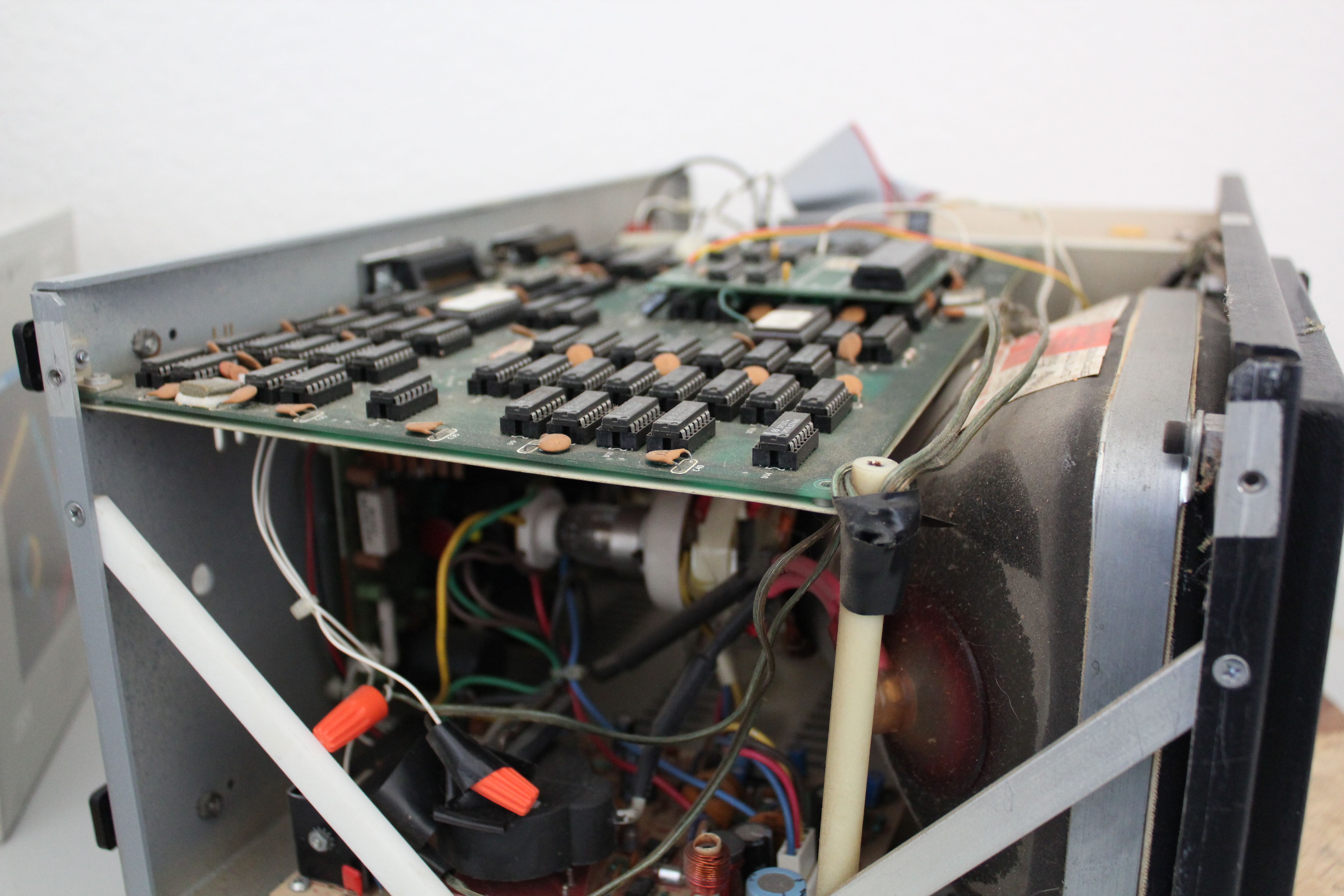
- Top view, showing the main board.
-
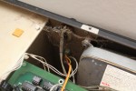
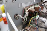
- Dangling cables from some removed upgrade.

-
- Most internal cables were left dangling, so I’m not assuming that anything works.

-
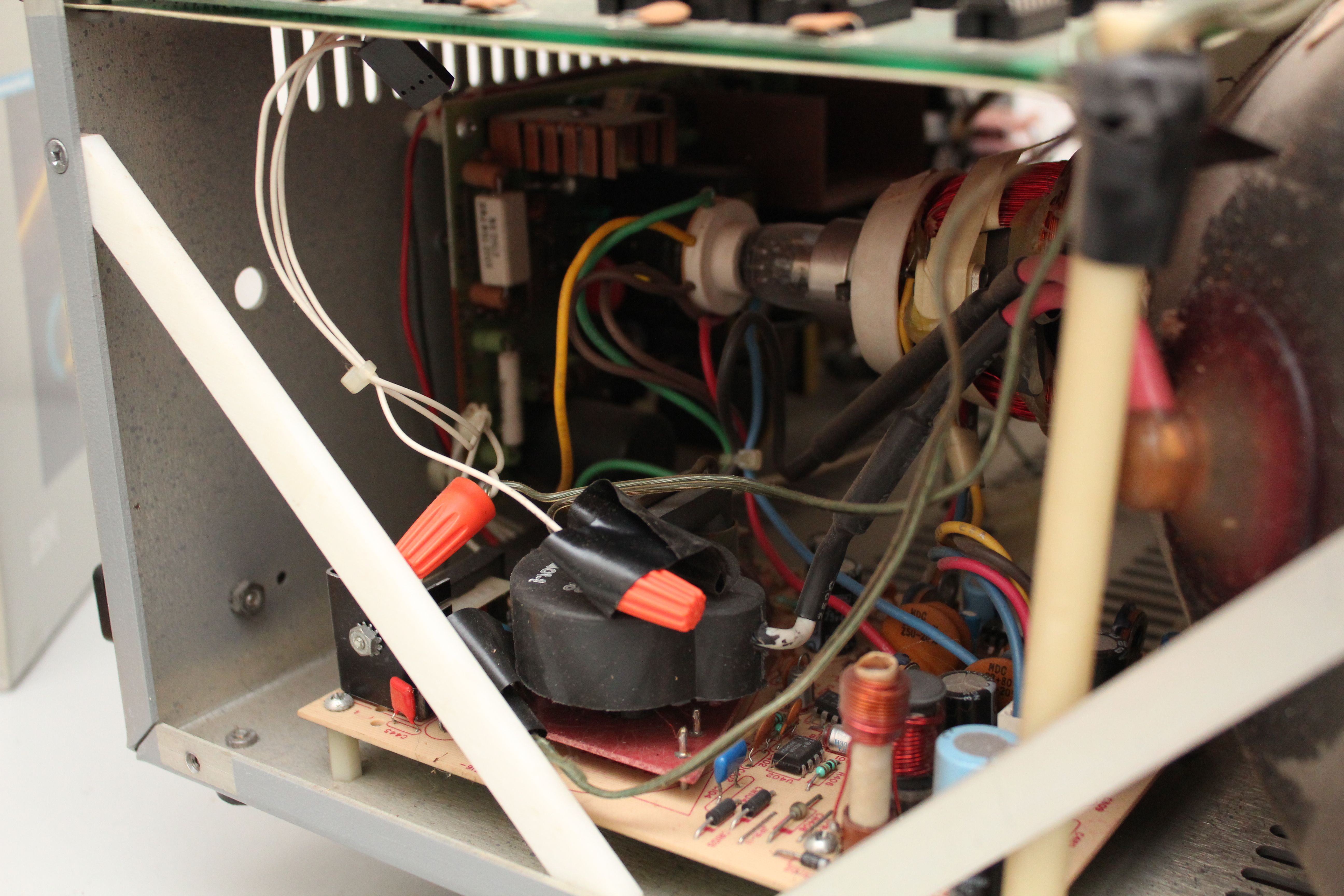
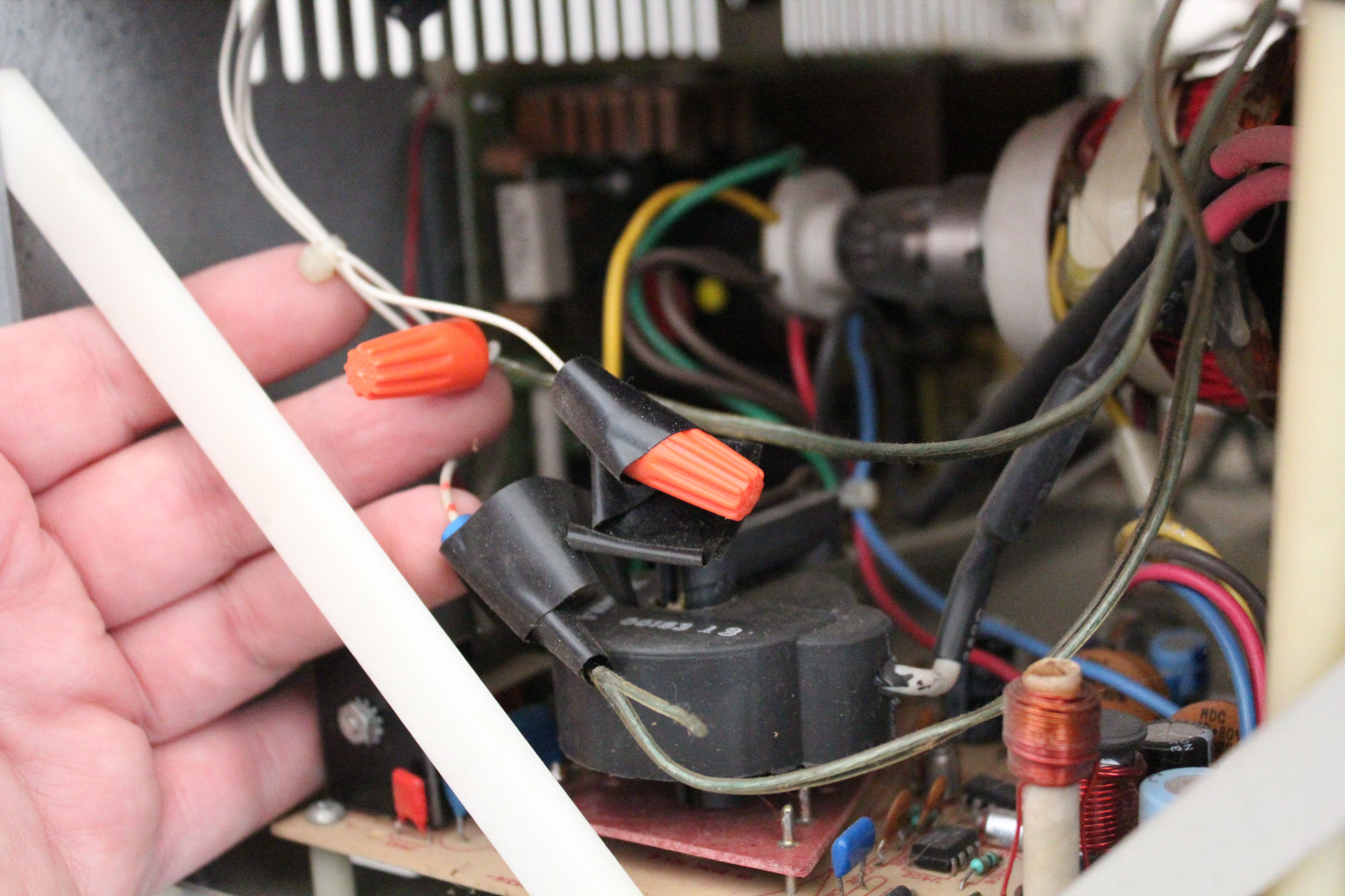
- Relocated contrast control is behind that spiderweb. Yes, that’s speaker wire connected to it. And yes, it’s carrying a video signal.

-

- Video connection spliced with wire nuts.
-
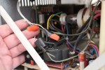
- Wire nuts. In the video path. I literally can’t even.
-

- Long standoffs are unscrewed, and have become dislodged. For some reason, there’s wood crammed in the top screw hole of one of them.
-
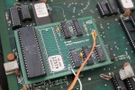
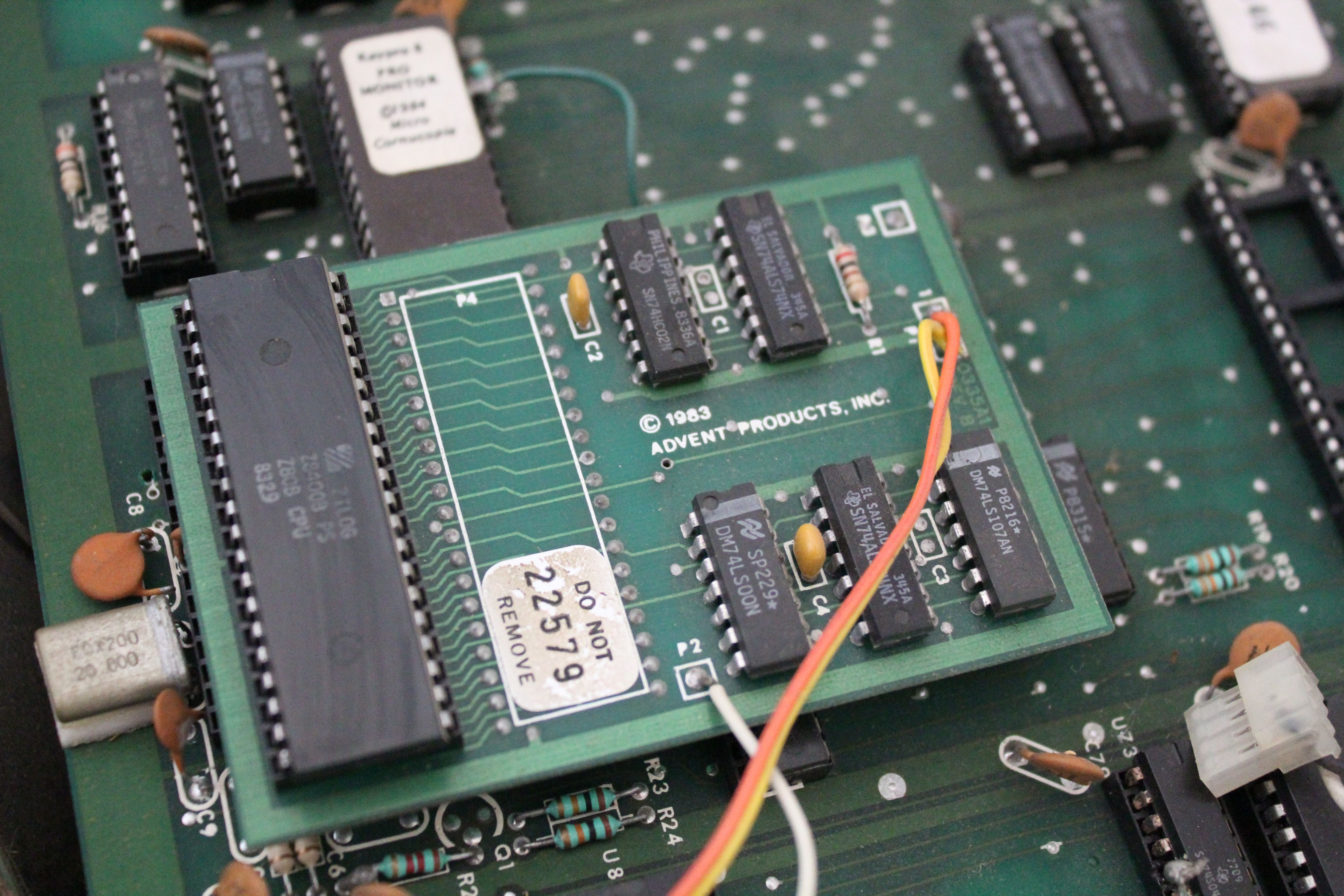
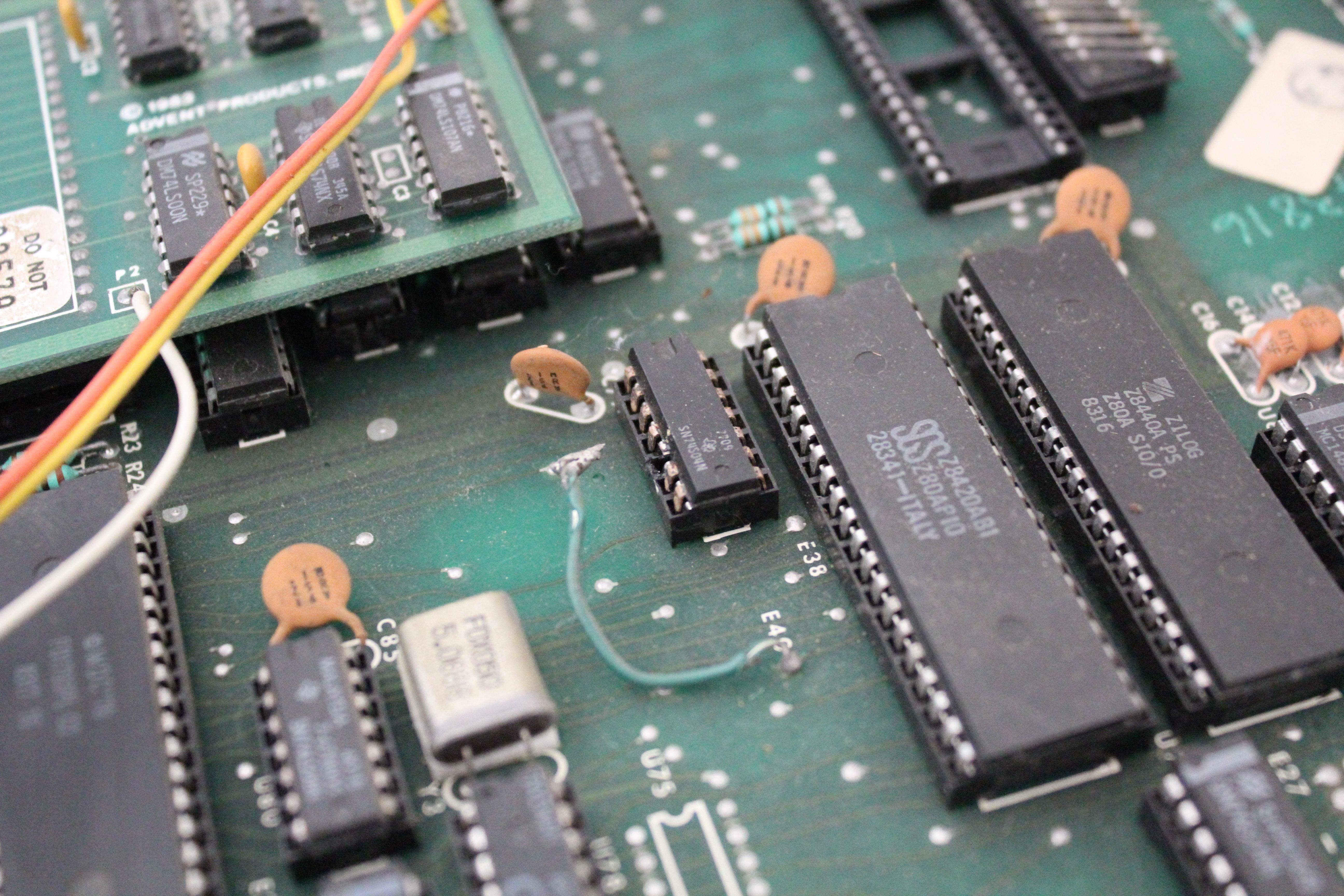
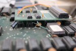
- Upgrade board has a Z80B on it, and is plugged in to the CPU socket. What does this upgrade do? It’s connected to a toggle switch on the front panel.
-

- Lifted pin has broken off, so I’ll need to fix this.
-
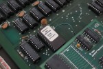
- Upgrade ROM. What does this ROM do?

-
- Lifted pin on upgrade ROM is wired to something. I’ll need to reverse-engineer whatever’s going on here.

-
- The contrast control (mis-labeled “BRIGHTNESS”) is back where it belongs, and the speaker cable and wire nuts are exorcised from this Kaypro II. Now I can sleep at night.
-
- I pulled out the top drive to clean it up. All three spindle bearings were seized, but I freed them up. Head sled also moved roughly, but smoothed out after I worked it back and forth.

-
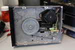
- The drive belt was stuck to the flywheel, but it came free without apparent damage.

-
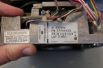
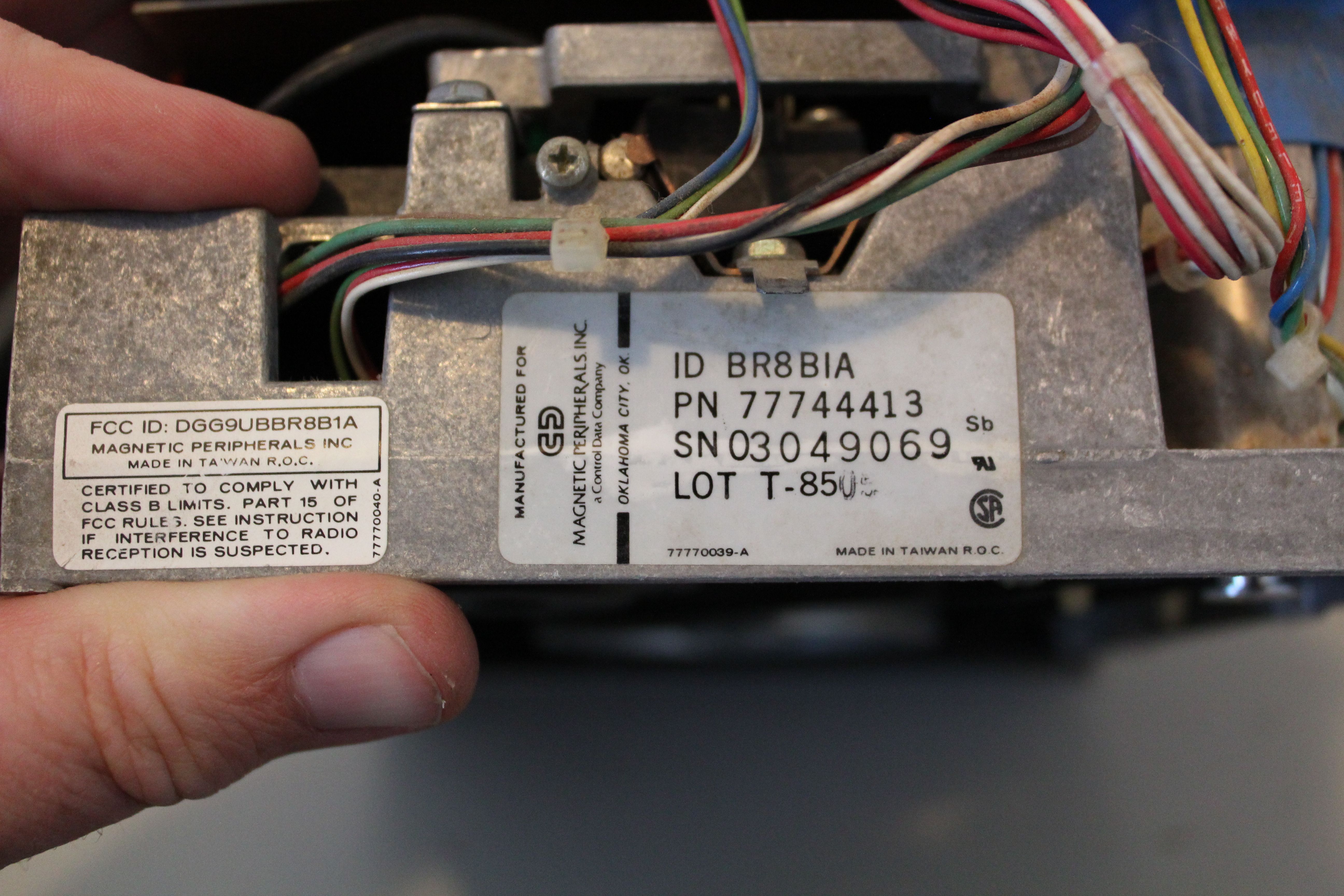
- It’s a Magnetic Peripherals Inc. drive.
Found this description of the “Kaypro 8” ROM… Pretty cool if you can get 4 drives in place instead of 2 at a higher capacity.
B] I upgraded, using Micro Cornucopia methods / parts of that era, all six [6] of our Kaypro II ‘s to Kaypro “ 8 “ ‘ s. This allowed “quad” disk drives – 720 K to be used – actually at half height, half power, four [4] could be added per Kaypro in place of two [2] Tandons. This was a tremendous improvement in many ways, since many early Tandons were not very reliable and, of course, much smaller capacity.
Mark,
Just an idea: You mentioned that the “front panel has a few holes for me to patch up.” If the front panel is black-painted steel rather than plastic, and you don’t do thin sheetmetal welding yourself, you could try an autobody repair shop and have them weld in patches (*only* in the holes that you mark). Then you can repaint the front and you’d never know the previous owner had butchered to machine’s front panel like he/she did (probably a “he,” but you never know).
Bob
The add on board plugged into cpu socket is a speedup kit. It allowed the early Kaypros to run at 4 or 5 mhz instead of 2.5. The switch would select between 2.5 and the higher speed because some software such as the disk formatting utility would not function properly at the higher cpu speed.
Also, If you dont want the speedup kit, i do. I have a kaypro IV 83 that needs one desperately.
I would trade the whole Kaypro II, including the speedup kit, for a working Tandon TM100-2A to replace the bad one in my Kaypro IV/83. The stepper motor is mechanically messed up in my bad drive, so it’s not the usual matter of replacing the belt and/or oiling dry bearings.
Is this offer still on the table? I have a perfectly-functioning Tandon TM100-2A in great condition that I would be willing to trade. It’s a “B:” unit with the blue resistor array IC.
Thanks.
Are you close enough that I wouldn’t have to pack and ship the Kaypro? I’m near Riverside, CA. And I expect to be up in Paso Robles, CA for a military radio collector meet at the beginning of May.