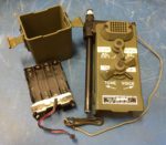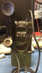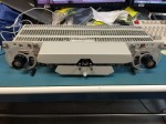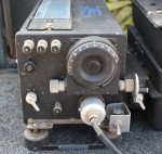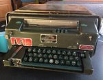
I got this AN/TGC-14A(V) Mite Teletypewriter at the 2019 Military Radio Collectors Group meeting. One of these days, I plan to mate it up with an AN/PRC-47 transceiver and CV-2455 converter to make an RTTY set like Dave Ross N7EPI (SK) used to operate at MRCG events. I think that his Mite was one of the rare as hen’s teeth models that was configured to be powered by 28 VDC. Mine is configured to be powered by 115 VAC 400 Hz, which is going to be a lot less convenient to produce… but at least it’ll be a power source which can also directly power the AN/PRC-47 set.
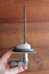
This Mite has a single external 12-pin connector. I believe that its connector is Amphenol part number 165-11, and the mating connector for it would be Amphenol part number 165-10. I don’t have any cables or mating connectors for it yet, and I don’t know if it works yet, either.